www.recumbents.com
10 kW
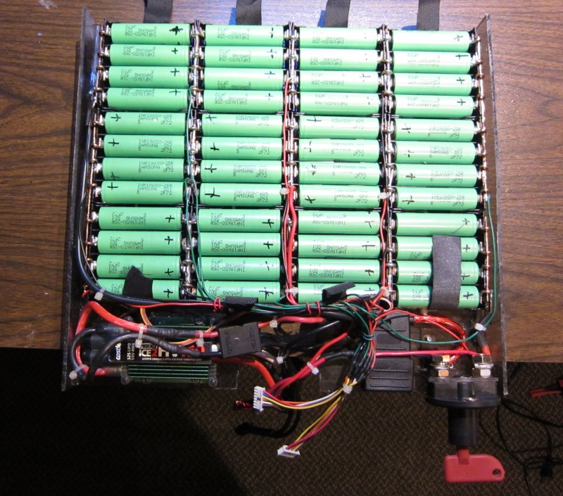
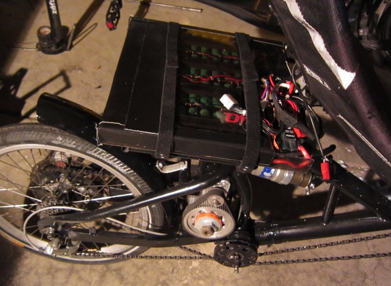
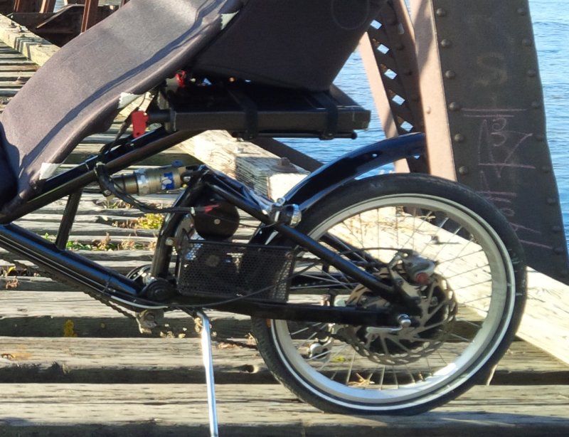
Over the weekend I finished the wiring for main power, charging, cell group testing and balancing. I added a switch and a fuse but could only find a 40A fuse for the holder I bought. I'll have to do some testing to see if that is adequate. I already know the system can pull up to 90A, but just for very short periods. The battery holder array, ESC, etc. are now attached the to the bottom of the plastic case.
I just need to add an LED to indicate power, load up the cells and then, test ride time!
I just need to add an LED to indicate power, load up the cells and then, test ride time!
")