
You are using an out of date browser. It may not display this or other websites correctly.
You should upgrade or use an alternative browser.
You should upgrade or use an alternative browser.
Nucular electronics - complete kit for ev!
- Thread starter VasiliSk
- Start date

Wheazel
10 kW
Looking forward to see how your rv160s mods turn out. Awesome work so far.
VasiliSk
1 kW
- Joined
- Apr 10, 2014
- Messages
- 420

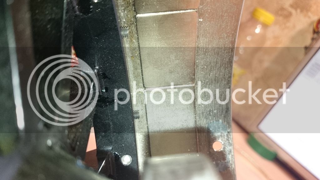
I was thinking about why thermal probe have so high lag... rigth side how it was installed. Red square exact diode location.
Quote from revolt:
Ha ha. i can see it actuallyTemperature sensor is installed between the windings directly in front of the hole, poured lacquer. You can't see it - it is covered with copper.
John in CR
100 TW
That's good news on the lams at least, because phase-phase resistance of 80mOhms. My Revolt 120 is just under 30mOhm. Can you please double check. Why on earth would they go Delta when trying to get to the relatively low Kv of 45rpm/v for that style of outrunner? I say go WYE for fewer turns and more copper on each turn, which should be easier to get good copper fill, and also no potential for "recirculating currents" side effects of Delta, something that's still a mystery to me.
How much did the no-load power change at 3k and 4k rpm with the new bearings?
How much did the no-load power change at 3k and 4k rpm with the new bearings?
sn0wchyld
100 kW
VasiliSk said:I've run some tests on rv160s motor. On this graph horisontal - rpm, vertical - power consumption...
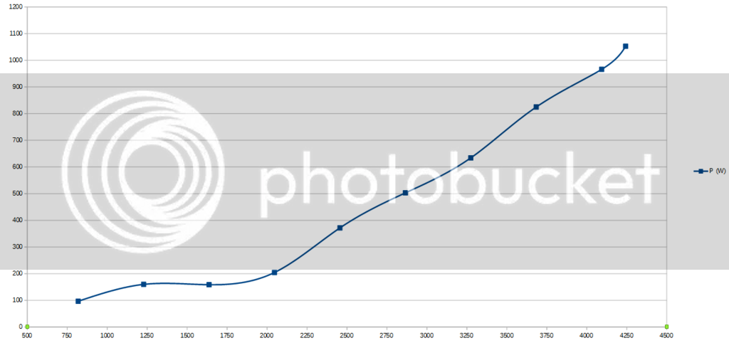
as you can see when motor runs 4k+ RPM, power rises above 1kW!! I have find out that main problem of such losses is a big bearing, it is heats up instantly when motor spinning 4k.
Here is explanation vid: https://youtu.be/qTRJ4jqASRA it is in russian, but easy to understand where is problems
So i replaced this original NSK 6814 bearing to NTN 6814, cover now spins much longer!!
And finally some photo of RV160s
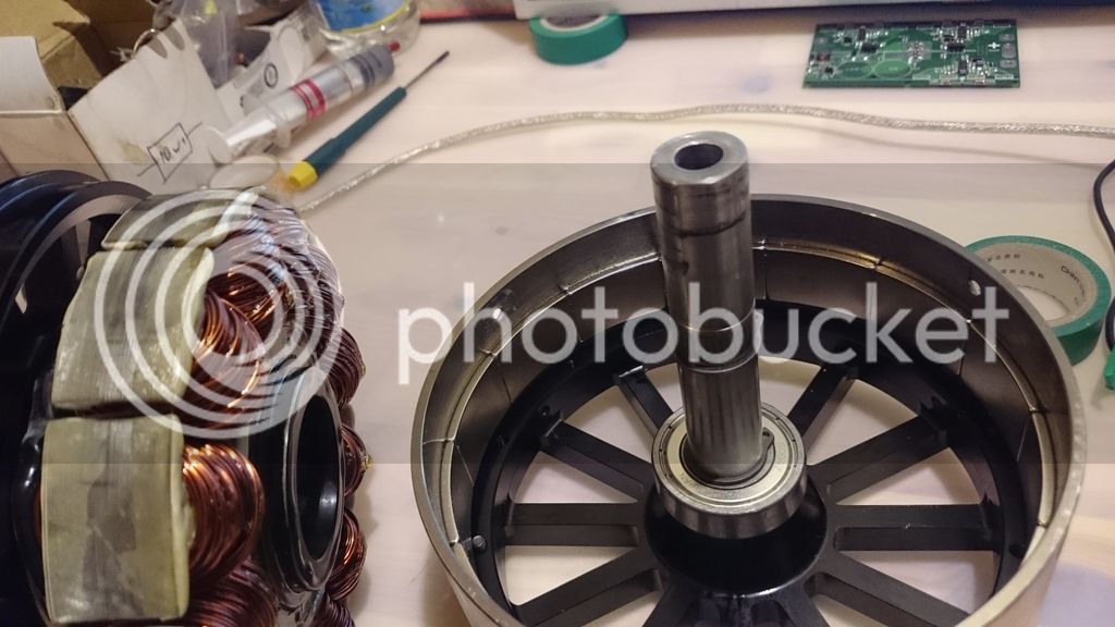
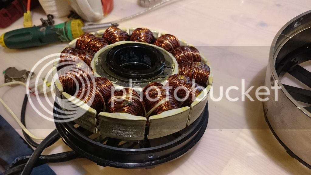
magnet width 25mm... winding NOT 6 parallel wire, but 5. im quite dissapointed with this motor
hows the rotor stability with the inner (wire side) cover removed? would it be at all possible to run it without the inner side cover, leaving one side open?
Wheazel
10 kW
Vasilis, how did you disassemble the revolt? I am concerned about the step when the magnets and stator shall be either separated and reinstalled.
How strong are the forces coming in play? I remember I did hurt myself on a 1kg rc outrunner many years ago when i was putting it back together.
How strong are the forces coming in play? I remember I did hurt myself on a 1kg rc outrunner many years ago when i was putting it back together.
VasiliSk
1 kW
- Joined
- Apr 10, 2014
- Messages
- 420
sn0wchyld i have some runs with this cover revoved. it is disbalanced, i will get another try later.
Wheazel here is guide from revolt
1) remove screws
2) pull out rotor, you can hook on red triangle, and pull on blue line
3) remove lock ring
4) hold stator, press out axle with rear cover. beware - bearings on glue
5) remove bearings from stator if you want
Magnets not really strong, but there is nothing to hold on to pull out rotor
Wheazel
10 kW
Thank you VasiliSk! Just what I needed to avoid guesses/assumption.
crossbreak
1 MW
VasiliSk said:Got this data from RV160 short
[..]
80mOhm
[..]
33.36kV (RPM/V)
[..]
this gives me 39.6Nm on shaft of motor with 180 phase amps
thx for that data and this graph about no load consumption. now we can add it to the comparison thread: https://endless-sphere.com/forums/viewtopic.php?f=30&t=65757&start=500#p1168909
so this motors Km² is only ~1
 weaker than the RV120, which gets 1.6 from what revolt told us. would be nice to hear what they say about these weak figures. The Rv120 short has Km²= 0.6 which is also very weak. Looks like the short versions aren't what we're after.
A MAC motor is Km²=0.66 for comparison (stack is 22mm and airgap dia is 135mm), so these specs given for this RV160-short sound reasonable, still disappointing if you look at its weight.
Wheazel
10 kW
VasiliSk said:After rewinding, Km should rise a lot
I am very intrested in seeing the rewind and the differences it will give.
Is this something you plan to do soon?


John in CR
100 TW
VasiliSk said:Yes, but after some tests. i need to find out optimal RPM
Optimal rpm? How can that be determined, and of what use is it unless you have long distance constant speed cruising.
Since you're rewinding anyway, and wanting to go sensorless, I'd suggest going 6 phase. ie Every other tooth on the stator goes to a separate 3 phase sensorless controller. Several reasons to go this route are:
1. The controllers will see higher inductance for the same Kv.
2. Controllers carry half the current.
3. You'll get a smoother start with sensorless control than with a single 3 phase controller.
VasiliSk
1 kW
- Joined
- Apr 10, 2014
- Messages
- 420
RPM will be determined depending on rotating lossess.
1) and? i have 20khz pwm, this is enough to handle even very low ind. motor
2) so... total lossess will be same if total used fets are same (6F+6F or just one 12F)
3) what?? smoothenesss depends only on controller startup current. i have several technique to hande low erpm, so this may be so soft as with halls. well, actually i want to say there is no matter what is source of feedback
John in CR
100 TW
Sorry I missed that you're using some type of sensors for startup. Going to sensorless once rpms are sufficient is great to avoid the issue of inaccuracies in the sensor placements. I hope you're right that the 20khz pwm frequency makes low inductance a non-issue, because it's been my understanding and experience with many thousands $ in blown controllers that low resistance low inductance motors driving high loads on startup reek havok on controllers beyond just the current handled by the mosfets. I have no choice but leave it to you guys with the electronics expertise to solve those issues.
Let me know if you're interested in going the route of higher voltage, and I'll throw some funds your way, because I need controllers that can handle the kind of current you're doing, but at real pack voltages approaching 150v-200v.
Let me know if you're interested in going the route of higher voltage, and I'll throw some funds your way, because I need controllers that can handle the kind of current you're doing, but at real pack voltages approaching 150v-200v.
VasiliSk
1 kW
- Joined
- Apr 10, 2014
- Messages
- 420
Well, i have perfect mosfet protection, you can even short phases and nothing will happen This saved me thousands of times
Mosfets are optimal for battery voltages below 130V (for 150V mosfet), anything higher - rapid rise of rdson. (even 100V mosfets looks much better than 150V). Only next voltage - is something in range of 400~800V for IGBT
And no, im not ready to leave this project, there is no time so much to do.
By the way i've tested charging 2500W through the motor (QS203 4 turn).
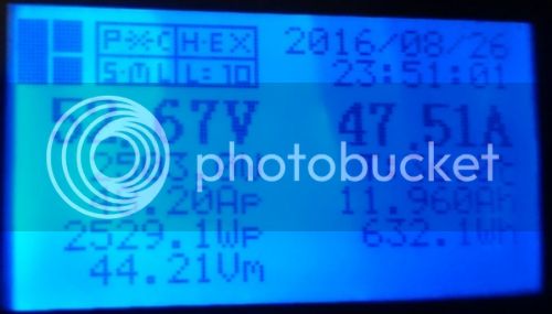
75C° on motor max, and 55C° on controller. No charging coil needed
This saved me thousands of timesMosfets are optimal for battery voltages below 130V (for 150V mosfet), anything higher - rapid rise of rdson. (even 100V mosfets looks much better than 150V). Only next voltage - is something in range of 400~800V for IGBT
And no, im not ready to leave this project, there is no time so much to do.
By the way i've tested charging 2500W through the motor (QS203 4 turn).

75C° on motor max, and 55C° on controller. No charging coil needed
larsb
1 MW
Hello, did you ever rewind the rv160? It would be really interesting to see before and after measurements compared to how much extra copper you could get in.
larsb
1 MW
Ok, good luck with the launch! I might try to rewind a rv120 later so i am looking for info.
VasiliSk
1 kW
- Joined
- Apr 10, 2014
- Messages
- 420
Hi guys, came up with a little update for you
I have started testing of my electronics kit in Russia, here some photos of this <beta> version:
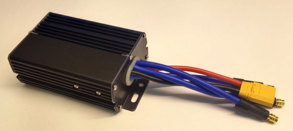
12F controller, up to 90V, 200Aph, 150Abatt. Well protected, good heat dissipation, compact size (like a 9F). BT4.0
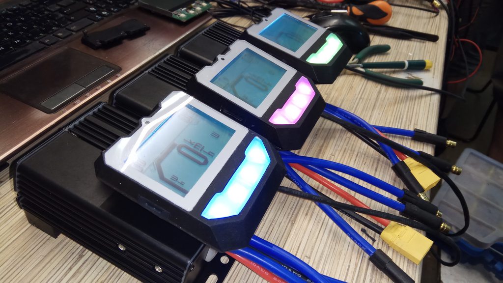
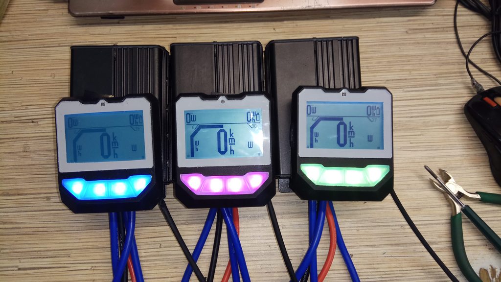
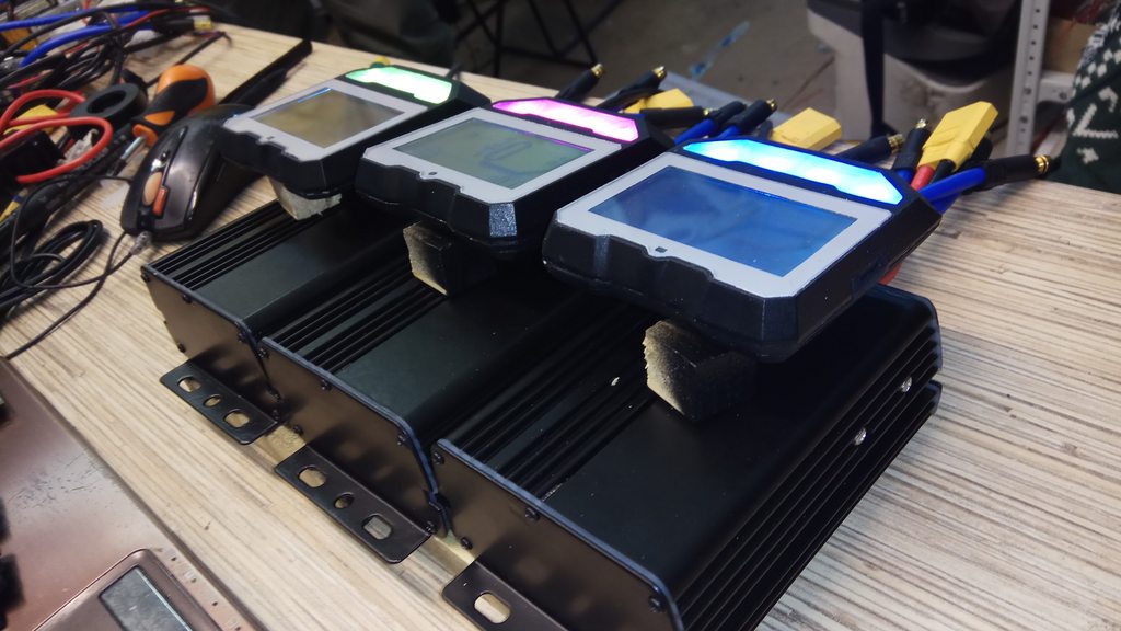
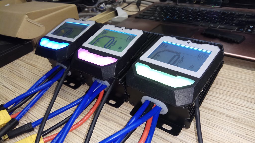
LCD, 240x128px 3", RGB button highlight, USB 2A charger, microSD slot for software updates
I have started testing of my electronics kit in Russia, here some photos of this <beta> version:
12F controller, up to 90V, 200Aph, 150Abatt. Well protected, good heat dissipation, compact size (like a 9F). BT4.0
LCD, 240x128px 3", RGB button highlight, USB 2A charger, microSD slot for software updates
Similar threads
- Replies
- 0
- Views
- 2,592
- Replies
- 10
- Views
- 2,035
- Replies
- 11
- Views
- 3,071
- Replies
- 8
- Views
- 2,595
- Replies
- 4
- Views
- 4,069