18650 pack - am I doing this right?

Synon

10 W
Joined
May 10, 2013
Messages
69
Location
Flagstaff, AZ
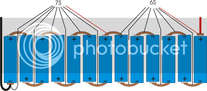
So I'm starting to learn how to build a battery pack from laptop 18650's, I'm still new to this and I want to make sure I'm doing it correctly and safely. The enclosure material is 1/4" PVC scrap I'm getting from work, the reddish material is copper that I'm hammering out from some 1" copper tubing I have. The grey is a battery clip that will be soldered to the copper (link to clips: http://www.mouser.com/ProductDetail/Eagle-Plastic-Devices/12BH209-GR/?qs=sGAEpiMZZMupuRtfu7GC%252bdsh6aXbLPoEMAiSg3BFBQo%3d). The bottom will look the same as the top.

I wanted to make this easy to disassemble and replace batteries without having to break apart the entire pack and soldering directly to the batteries. This pack should give me 22.8Ah at 48v (ideally) with the batteries I have. I'm looking for feedback on the design and if I'm arranging these correctly. I still haven't done any research on how the balancing leads need to be connected, so information on that would be much appreciated as well!

4u2yBas.png
 
Couple of observations (note, I've never done this myself).

I don't think I'd trust spring loaded terminals in a ebike situation, batteries get bounced around a lot and I'd be concerned about them not making great contact.

Also, how do you plan to hammer 1" tubing to be less than 18mm wide? Or are you planning on cutting it into strips after you hammer it flat?
 
I wouldn't trust spring loading them either...

I've used spring loaded 4p holders for charging cells... some of the springs have glowed red and melted through the holders in seconds
(due to a bad cell etc...)

if you're determined to do it that way... you need a sheet of something strong top and bottom to clamp all the cells in tight.... really tight.... bolts around the sides and through the middle too


google (and search on here too) for battery tab welders, they're cheap and easy to make... ok it's harder to replace cells... but it's not the end of the world
 
If the bottom bus bars are the same at what is shown on the top, seems to me you're shorting all the cells. The top bus bars I'm seeing in the pick looks wrong to me, you're going from the + of the first cell to the - of the second cell and then from the - of that second cell to the + of the third cell. That's not how series connections are done. The balance wires are not right and I don't understand why your negative and positive leads end up at the same end of the pack.

If my eyes don't deceive me, you're making a 13S8P pack. Here's how I would wire it, looking at the pack from the side so you see the end of each 8P strings. I split the balance leads into 7S and 6S if you plan to use a balance charger to balance your pack. This would work for a charger like a Hyperion 1420i. If you plan to use something like a BC168 then you need to have three balance leads, a 5S and two 4Ss for example and you balance charge each one after the other.

13s_18650_zps9e35d277.jpg


I hope this helps and I hope I didn't make a mistake in my drawing to make me look like an idiot :lol:
 
That looks good to me too, once I got it that you were looking at the end of the pack. It's essentially the same as in the top drawing.

I would tend to agree, that you need to spot weld tabs to the cells, then solder or whatever on the tabs to connect the parallel strings. Then you could go to bolt connections or whatever for each string. Couple flaky spring connections, and suddenly you are pulling 2c from .5c cells. Ruh Ro.

Make an extra paralell string, so a weak string can be easily removed for diagnosis and replacement of cells in that string, while you keep riding on the spare.
 
mistercrash is right, you've shorted out all the cells in the diagram.... I missed that at first

this is how it should be
4u2ybas.png


bit of a quick and dirty edit, but you get the idea

the bottom of the pack should mirror that, so where the cells aren't joined on the top they're joined on the bottom instead :)
 
Back
Top