A123 capacity vs charge voltage (and other effects)

The Mighty Volt said:
Is it fair to say that smaller battery packs, say 24v 10Ah, with therefore fewer cells, are easier to keep balanced, and therefore harder to pull out of balance, than larger packs using more individual cells?

I would think so, but only because there are fewer cells to go wrong. If the chance of a cell going out of balance is say 5%, a 4S pack has a 20% chance of going out of balance (1.05^4). A 12S pack would have an 80% chance (1.05^12).

And the series count is more important than the parallel count. Paralleled cells tend to average their charge balance.
 
texaspyro said:
The Mighty Volt said:
Is it fair to say that smaller battery packs, say 24v 10Ah, with therefore fewer cells, are easier to keep balanced, and therefore harder to pull out of balance, than larger packs using more individual cells?

I would think so, but only because there are fewer cells to go wrong. If the chance of a cell going out of balance is say 5%, a 4S pack has a 20% chance of going out of balance (1.05^4). A 12S pack would have an 80% chance (1.05^12).

And the series count is more important than the parallel count. Paralleled cells tend to average their charge balance.

Thanks. :D
 
I did some testing to determine the A123 cell voltage that indicates 90% discharge. Unfortunately it seems to depend upon the cell discharge rate (or perhaps temperature).

At 1C a voltage of 3.075V was a good indicator there is 10% capacity left.
At 5C the voltage was 2.850V
 
texaspyro said:
I did some testing to determine the A123 cell voltage that indicates 90% discharge. Unfortunately it seems to depend upon the cell discharge rate (or perhaps temperature).

At 1C a voltage of 3.075V was a good indicator there is 10% capacity left.
At 5C the voltage was 2.850V

Thanks for the effort Texaspyro. I've gotten spoiled with the LiMn Konion cells with no balancing (I haven't even checked for balance in over a year now.), and being able to use voltage as my fuel tank gauge. The big news for me is your original info in the thread, ie that nearly full A123's can have a pretty wide voltage range, and all we have to do is get them to 3.45V and they're all full. I just need to retrain myself and switch to wh used compared to capacity as my fuel status. Hopefully with cell matching I can build a pack that's relatively fuss free, which I think is possible with target max discharge levels of 60-80%, though I definitely won't attempt to just solder them up with only +/- pack leads and seal them up like I do with the Konions. Balancing taps and periodic monitoring will be part of the plan, but hopefully once I get them in regular use that balancing etc can go to once every week or two, but only the early frequent monitoring can tell me that.

Your temperature data at only moderate discharge rates concerns me though. Are you sure these are A123 originals and not knockoffs or QC rejects, and that they aren't extremely worn out cells? I want at least 30C peaks, not even the stated 30C continuous without hot packs.

John
 
I am using both cells that I recovered from DeWalt packs that had broken BMS units (the cells were not affected) and new A123Racing cells from A123 developers kits that I got from Hobby King. I measured the cell internal resistances and they are good.

The A123 cells have around 0.010 ohm internal resistance once you get them connected. At 12 amp discharge that works out to 1.44 watts of self heating and a 0.12V drop. The cells weigh 70 grams each, so that temp rise is probably valid. I am going to do a better measurement of the 5C discharge with the cell in an insulated unit and the thermocouple in better contact.

Do you want 30C from a paralleled pack or a cell? Drawing 70 amps from a single cell is not a good idea... 50 watts of cell heating and 0.7V drop right off the bat. 70 amps from a 5P pack is a whole 'nuther story...

A123 cells are spec'd at 60A which is 26C. At that rate self heating will quickly raise their temp over 140F which is where the cells get damaged and their lifetime drops to zip. To keep them under 140F, you need to limit the discharge to 12C at room temp. The paper that CellMan posted in http://endless-sphere.com/forums/viewtopic.php?f=14&t=20698#p301951 has some nice plots and info... particularly the plots at the top of page 5. My temps look a whole lot like theirs...
 
I did the 5C (12 amp) discharge test with the cell in an insulated container. Here is the voltage curve:


The cell temp every 100 seconds:
0 73.5F
100 78F
200 83F
300 88F
400 92.5F
500 97F
600 102F
650 105F
675 106.8F
 
I'm looking to get at least 120A peaks out of a 4p pack, so I should do some ventilation or broaden the pack.
 
I updated the first post with the data from some of the later posts.

I also added the 5C discharge tests on a cell that had been chilled to 5 degrees F and then discharged at the 5C (12 amp) rate... very interesting. Note that the cell was removed from the freezer and immediately discharged in a insulated container. No attempt was made to keep it chilled.
 
John in CR said:
I'm looking to get at least 120A peaks out of a 4p pack, so I should do some ventilation or broaden the pack.

Well, I would not build the pack into a sealed beer chest... I have seen some reports of using an air scoop to force air over the pack that was rather effective in cooling it. A little air flow can go a long way in keeping heat at bay. Also, radiative heat flow goes up at the FOURTH power of the temperature difference. (and while we are talking about arcane physical power laws, the noise of a turbulent air flow goes up at the EIGHTH power of the velocity)

If your outside temp is 100F and you want to keep the pack under 140F, it looks like you can average an 8.7C (20 amp/cell) discharge rate, open air, without any cooling. In a 4P config, 8.7C is around 80 amps. Heating goes up with current squared, so you can't do those 120A peaks for long at 4P, but it should be doable. A 6P pack should allow around 120 amp continuous discharge.

For most electro things (including batteries), every 10 degree C temp decrease doubles the life...
 
I built a 7C (16 amp) load for my battery tester mod for the welder out of 4 of those 0.7 ohm Dale 50W resistors. Result was 0.177 ohms.

I discharged an A123 cell into it without any cooling... it got freakin' hot... really freakin' hot... I then measured it while it was toasty and it had shifted less than 3 percent. The uncooled 5C sand resistor load would change over 20% in that situation.

I added some 7C data to the first post. Also updated the capacity vs charge voltage table with a couple of new values.
 
Great work there. I can use that info in my BMS design.

I like how the freezer cells start out low, then the voltage actually increases as the cells heat up. This could happen in a real vehicular application if the battery compartment is somewhat insulated. Battery heaters might be a real good idea for those Canadians too.
 
thanks for adding the values between 3.30 - 3.35v
3.45v is the float charge, exactly what I was seeing
 
The Killacycle people include heaters in their packs, but for a different reason. The cells are more efficient when warm and can discharge at a higher rate when warm.

If you live in icicle land, I would definitely insulate the cells. They really sag when it is cold. Something like pipe heater tape might be good to preheat the pack before you leave off into the woodsy way. If your pack had the extra capacity, you might try a self-powered heater.

I'd also like to test charging at cold temps, but don't have a good way to do that right now. A walk-in freezer would be handy...
 
with the level of capacity in the 3.35 - 3.4V range
what would be the fast/minimum charge time ?

texaspyro is correct more mah at low voltage ??
(original first post)
3.45V -> 2268 mAh
3.40V -> 2274 mAh
 
myzter said:
texaspyro is correct more mah at low voltage ??
(original first post)
3.45V -> 2268 mAh
3.40V -> 2274 mAh

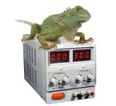
Capacity differences that small are pretty irrelevant. They can be due to temperature, timing, moon phase, random noise, gremlins, etc. Maybe even that lizard that likes to sit on top of the power supply has been monkeying with the controls.


I am charging the cells (outside) with a 6 amp HP lab supply. I don't have an easy way to time completion of charge other than sitting there with a stopwatch (ain't gonna happen). I hook it up, go away, come back, disconnect when the amps are low (usually down to 0 by the time I get around to checking it). With a normal 3.65V charge voltage, it takes under 30 minutes. I know at some of the lower voltage settings, I went to lunch, ran some errands, came back three hours later and it was still charging.
 
A friend from England was visiting yesterday. It started to rain again (we had over a foot of rain in 24 hours), so I switched on the TV. Oh, that's nice... there's a tornado in town, only a few miles down the road. My friend said that he had never seen one. I replied, well just wait a couple of minutes, it's coming right at us. He laughed and said "Yeah, right". Two seconds later the warning sirens went off. There is one only 100 feet from my house and it is real horror-show LOUD!. :twisted:

Two questions for our British friends: 1) How do you get British crap out of pants and off floors? 2) How do you get cowering British friend to come out of the basement? :twisted:

I stayed outside and watched... the tornado had lifted up about a mile from the house and went almost directly overhead. Now I have frogs in the swimming pool...
 
I added a plot to the first post of the cell behavior after being fully discharged to 2.500V with a 1C load. After discharge the load was reduced to 4 milliamps and the voltage was recorded and plotted over several hours. After 1.5 hours the cell voltage peaked at 2.75V. After 9 hours the cell voltage had fallen back to 2.500V.

Basically the cell had around 40 mAh of residual low capacity charge after being drained at 1C.
 
texaspyro said:
Oh, that's nice... there's a tornado in town, only a few miles down the road.

Weather events are fun! (At least to a point) Us Europeans are used to whimpy weather, but 10 years in the states taught me otherwise. Snowstorms in the NE (stuck in car at -40), hurricanes in the south, downpours etc.

Good reminder to be prepared. Keep batteries charged and a kerosene light and some alternative means of heating/cooking in case the power is out for a few days.
 
jag said:
Good reminder to be prepared. Keep batteries charged and a kerosene light and some alternative means of heating/cooking in case the power is out for a few days.

20 KW natural gas/propane powered standby power generator wired to automatic transfer switch... keeps the guest house comfy when the 'lectrons stop flowing... Life without electricity just plain sucks...
 
I added some very interesting info to the end of the first post concerning the long term self discharge rate of A123 cells.

Also info on how they behave during a CC/CV (constant current/constant voltage) charge cycle.
 
Just stumbled across this most excellent thread. Thanks Pyro!
By the way, I guess your British friends were from the south. There's no way a notherner would have been cowering in a basement if there was a chance a pub had had its doors blown off... :D

A while ago I tweaked the high voltage cutoff resistors on my Fechter/Goodrum BMS so that charging finishes at 3.50 volts. The main reason maximise cell life and reduce charging time. I originally found that with my setup if one cell finished a little earlier than the rest it would overshoot the cutoff point and reach 3.9–4.0V for a little while. I also didn't like the idea of holding most of the cells for long periods at 3.75V while latecomers were catching up. It's good to get confirmation that I've lost little capacity by doing so (assuming these results extend to LifeBatt cells).

The low temperature performance results are also interesting, especially to weather-challenged Brits. The quick way to warm up cold cells would be to use wide open throttle for the first few minutes, though I have a feeling that sort of treatment wouldn't contribute to the longevity of cells.
 
Malcolm said:
I originally found that with my setup if one cell finished a little earlier than the rest it would overshoot the cutoff point and reach 3.9–4.0V for a little while.

Once a cell reaches that kind of voltage, it prevents the lower voltage cells from charging. Then the pack gets really unbalanced. And then those people running without a BMS or cell balancers wonder why their packs died...

A cell balancer that works during the charge cycle should help prevent that. I have been playing with a switched capacitor balancer that can run while the cells are being charged, discharged, or even sitting idle. See http://endless-sphere.com/forums/viewtopic.php?f=14&t=20864&start=30#p311026

Although the balance currents it generates are rather small, it seems to do a good job keeping the pack balanced. Because it can run while the pack is being discharged, it helps keep the pack from becoming unbalanced to begin with.

Switched capacitor balancers do not waste pack energy as heat like resistive balancers. If the pack is balanced, the standby current is very small (like less than a milliamp). If the balance clocks are not being generated it is a few microamps. I am still playing with the firmware in my clock generator chip. I think a good strategy may be to run the clocks whenever the pack is being charged or discharged and maybe for 24 hours or so after removal from the charger.
 
Back
Top