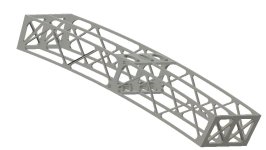
Any engineering geeks? 3d printed frame

Hephy

1 mW
Joined
Aug 24, 2019
Messages
10
owsj-frame.jpg
I was bored yesterday, old roll of carbon impregnated petg was screaming use me.

So v1 was 323g of material.

3mm square tubes 75mm tall 'joist', that's a 10mm arch on 500mm span. (8mm arrow shafts for interconnection at center). Not shown outer walls were included at .25mm

Printed with 1mm walls, 4 top and bottom layers at .25mm so 1mm all around the tubes. 10% infill just because I failed to turn it off.

That worked - supported my 240lbs. But bouncing - not so much :lol: broke along the top of the joists surprisingly (point load? Didn't have a top or bottom cover)

So pictured above now moves the open web joists out to 5mm square As usual printed carbon fiber filament there's not a lot of data useful for fusion's FEA module (probably not bad thing, that's probably way outside my skillset anyway)

Curious with all the minds around here - anyone put some thought into this style construction? With the 1mm nozzle on I printed the first test off last night - can make for quick iteration designs.

In some ways I know its a terrible idea. But it is so much cleaner and less smell than laying up true composites... If a redneck engineer like me can support my not insignificant weight - I do wonder if this couldn't be improved on.

Thoughts?
 
I'm not sure, what's supposed to be the purpose of this frame?
Do you have any picture of the print itself?

I'm fairly certain it is possible to build a very solid frame for a scooter/motorcycle out of a plastic 3D printer using filament... But you really need to overbuild it. Lattice structures like you designed won't handle anything else than some light static loads.
You also need to use a big nozzle, at least 1mm or even 1.2 if you can. This makes a huge difference in terms of strenght. I generally print my layers at half the nozzle diameter, so 0.5mm for a 1mm nozzle and 0.6mm per layer for a 1.2mm nozzle. The more layers you have, the weaker your part will be (but you don't really want to go for more than half the nozzle diameter because then the strenght will start going down again).

From my previous experiences, carbon doesn't make much of a difference versus classic PLA, but maybe some suppliers are better than others, I don't know.

Some design tips if you want really solid big prints:
-Overbuild everything. Sure it doesn't look as nice but it's really not an option. Avoid latices and such, avoid sharp angles too and always consider how the layers will be oriented regarding how the forces will be applied.
-Use the biggest nozzle you can. You'll loose details but gain A LOT of strenght. You can always make it look better and even add a bit of strenght later with a bit of resin/sanding or even a carbon fiber wrap.
-Use several perimeters, I'd recommend at least 3.
-Infill does matter a bit, especially with big nozzles. If you want the part to be really solid then you should crank up your infill level adnd infill overlap
-Increase printing temperature. It won't look as nice but it will improve bonding a bit.

I've made some extremely tough parts using my giant 3D printer, capable of handling a lot of weight. Never tried to make a vehicle chassis out of it yet but this idea has crossed my mind a few times... Maybe one day...
 
I was curious if I could build something to support my own weight. Semi sketched out as a center section of a kick scooter add fork mount to one side swingarm to other (simplified pretty sure I'd need to bring the swingarm support back a ways). 500mmx 200mm center section, if I could support my weight then there was point in continuing to play.
.
PLA is a non starter. PETG with carbon (yes no idea if it's powdered or small strands, typical Chinese manufacturing vagueness) had some chance, still stiffer/stronger than PLA and stable. I ran a 1mm e3d nozzle X, .25 later height as it's a good mix of strength and looks decent. 255° @ 30mm/s with 10% cooling. Thermistor reads high

It's funny the argument between monolithic blocks and lattice amongst 3d printing people. I've seen both ends of the spectrum work. I'm still in the walls and layers make more strength than infill camp clearly. There's some areas where individually each might work better.

I tossed the first one, without pics, was just going to walk away (destroy all evidence I tried). Then came back, thinking more about it. Pretty sure I'll give version 2 a try here this weekend. Curiosity is still getting the better of me.
 
flat tire said:
Yes, or maybe, but not with a filament extrusion printer.

Wouldn't say not possible.

https://www.fabbaloo.com/blog/2019/7/24/basf-launches-steel-filament-ultrafuse-316l

FDM printed then sintered in a kiln - true 316 stainless. By basf no less, with proper engineering data. The new material options are interesting - like that markforged that lays in fiberglass/carbon tow as it prints.

Heck if I'd annealed the first version it likely would have held up better.
 
You can't anneal PETG, only PLA will gain from that.

However as mentioned earlier, use more perimeters for stronger parts use 4 or more, it will do way more than infill.

I have tried printing with pure PC and that was really hard to break but also hard to print, some are printing functional parts in PEEK and similar that would absolutely work for structural/functional parts but they require extreme temperatures (E3D has some super heaters and heat beds.)

But I do believe printing parts is viable for e-scooter etc, I have done a few things for my E-scooter (new mount for display and cable management) and will do more when I have time and new ideas.
 
spid said:
You can't anneal PETG, only PLA will gain from that.
PETG anneals, perhaps the chemical process is different than PLA but there's definitely benefit (but also a higher temp needed 150° vs 120ish). There's parts I print regularly that are definitely stronger after, and supports break away cleanly after annealing.

I ran these with a 1mm nozzle, so 4mm walls would be insane.

Yes e3d convert here, titan aero with volcano is the primary printer. Huge difference from the clones.

Have peek and PC, I was curious more on the lower cost end for this attempt to see whether there was even a point to continuing
 
Hephy said:
I was curious if I could build something to support my own weight. Semi sketched out as a center section of a kick scooter add fork mount to one side swingarm to other (simplified pretty sure I'd need to bring the swingarm support back a ways). 500mmx 200mm center section, if I could support my weight then there was point in continuing to play.

Not really, no.
Anything can hold static weight, such test don't mean anything. A frame will have to bear impact and torsion forces, which are far, far greater than just static ones.

Hephy said:
PLA is a non starter. PETG with carbon (yes no idea if it's powdered or small strands, typical Chinese manufacturing vagueness) had some chance, still stiffer/stronger than PLA and stable. I ran a 1mm e3d nozzle X, .25 later height as it's a good mix of strength and looks decent. 255° @ 30mm/s with 10% cooling. Thermistor reads high

I can't say, maybe you got some better material than I did.
PLA has the advantage of being stiff, which is an interesting characteristic for a frame. But if you got some better material then go for it, of course!

Hephy said:
It's funny the argument between monolithic blocks and lattice amongst 3d printing people. I've seen both ends of the spectrum work. I'm still in the walls and layers make more strength than infill camp clearly. There's some areas where individually each might work better.

It's just a friendly suggestion based on my experience. In the end, it's not my head that will scrape the ground if/when it breaks. :lol:
Infill helps a lot with torsion, especially with big nozzles. I totally agree on the fact that it doesn't matter that much on smaller nozzles. Big prints are a different game.

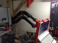
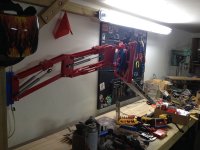
You can see hereunder a laptop support I made last year, and in my opinion a good example of "high dynamic loads" applied to relatively big 3D printed parts (each arm is around 300+mm long). Please note that in this case, the "high loads" will be absolutely nothing compared to what you plan on doing... As you can see it's quite a beefy design, it was entirely printed with my 1.2mm nozzle, 3 perimeters and .6mm layer height. Well I still had some parts who did broke (fixed since by beefing up some key parts and much higher infill).

My advice would be: start beefy and then, progressively, remove the extra/unneeded material.

IMG_5268.JPG
 
The cf-petg we have here is much stiffer than standard petg. And it's a lot stronger than PLA. Varies by manufacturer.

The last thing I put together with long arms like your laptop stand I was able to half the arm diameters by adding holes down the length on the horizontal axis. Took more than half the material out, dropped print time radically and supported more than double weight that was a struggle with the original slab design.

Yeah I've started on the light end of the spectrum, but I'd rather start from inadequate and beef up than overkill and try to reduce.
 
Hephy said:
The last thing I put together with long arms like your laptop stand I was able to half the arm diameters by adding holes down the length on the horizontal axis. Took more than half the material out, dropped print time radically and supported more than double weight that was a struggle with the original slab design.

Adding holes indeed makes the thing stronger, since you get more perimeters. But it does make the print longer, for the very same reason (more perimeters, which are generally printed at lower speeds), plus more top/bottom layers, plus more interfacing infills, travels and such.
That was actually the reason why I didn't make holes, it was taking more time to print :)

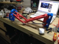
This one here under was the first version I made, it was more similar to a lattice structure as you can see. It worked fine, but was way, way less rigid than the new version.
IMG_3816.JPG
IMG_3841.JPG
 
Guess that depends on your slicer and jerk settings. I've got the heavy Titan aero with volcano and fullsize not pancake stepper.

I'm way faster printing walls than infill - direction changes are evil. That's why I run a big nozzle on most prints - single wall big layers. No infill. As soon as I start adding infill my times double+
 
Hephy said:
Guess that depends on your slicer and jerk settings. I've got the heavy Titan aero with volcano and fullsize not pancake stepper.

I've got 2 huge steppers that push the same filament together at the same time through the nozzle. Those are the biggest ones I could find for this format. They can push the filament with tremendous force, so I just have to crank up the temperature on my volcano water cooled print head and I'm basically not limited by the extrusion speed, only the elasticity of the filament becomes an issue at very high speeds for some inner corners.
Generally I run at 80mm/s for the inner perimeters, 50-60mm/s for the outer ones and 100mm/s for the infill. That's kind of the limit if you want layers to "freeze" before being dragged over by the head due to the elasticity of the melted filament.
Acceleration is currently set to 3000mm/s2 which is quite impressive to see given how big and heavy the printer is. Forgot how jerk is set currently but it's fairly high, the printer barely slows down unless the corners are very tight. My goal when designing this printer was to go for the highest possible speeds so most settings are chasing towards that aspect. :wink:

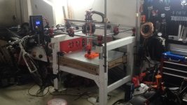
Here is my printer BTW:
IMG_4975.JPG

The build thread if you're interested :)
https://www.v1engineering.com/forum/topic/my-mpcnc-made-in-china/

Hephy said:
I'm way faster printing walls than infill - direction changes are evil.

That's not really normal, unless maybe if your acceleration is set to a very low level. You can go much faster in the infill since you don't really have to care about how it looks like. The only important thing being that it needs to merge well with the walls, so you just need to fix a decent acceleration then find the best infill overlap.

Hephy said:
That's why I run a big nozzle on most prints - single wall big layers. No infill. As soon as I start adding infill my times double+

That works well for some parts, although it's not great for the top layers, but I thought we were discussing about making a vehicle chassis here.
Anyway, we'll see. I hope you'll be right in the end, that would save some plastic and printing time. :wink:
 
Probably, all comes down to setup. Mine was an off the shelf cr10s once (now it has 6 friends). Most of my prints are functional so 30-40mm/s with minimized layer lines and ringing was my goal (was doing a lot of engineered test samples, they don't like that wavy wall issue so slower, more precise, better layer adhesion)

The frame on your mpcnc is neat. Probably wouldn't work for routing though. (I need a smaller desktop router, that I can enclose - like my old momus, so I'm less limited in hours it can run - another side project lol). I have a 24in² MPCNC.

Doing a quick redraw again today, pushing to 10mm structure, still in the general OWSJ structure, reworking the connections again. Then I'll print again and test.
 
Hephy said:
The frame on your mpcnc is neat. Probably wouldn't work for routing though. (I need a smaller desktop router, that I can enclose - like my old momus, so I'm less limited in hours it can run - another side project lol). I have a 24in² MPCNC.

Nice, a fellow MPCNCer!

My setup actually works ok for routing too, I have a milling head which is much shorter than the printing head. I just move up the mobile bed so that it is as close as possible to the gantry, which minimizes backlash. I can switch from printing to milling in a few minutes. So far I've been able to mill wood and aluminum successfully, it all comes down to the CAM settings. :wink:
 
Back
Top