dnmun
1 PW
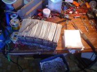
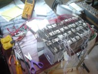
i saw there are some pictures on my disk from working on some chargers and disassembling some ping packs so i thought i would post them up since nobody ever takes them apart so they don't know what's inside.
the larger kingpan and EMC chargers use a bigger switching transistor format. like the TO-247 package instead of the To-220 package on the smaller chargers. this is 200V 15A. the collector is the tab and middle leg and the emitter is the left leg and base is the right. i just measured the npn transistors on corbins charger and it is 585mV forward bias from base to emitter in the circuit. collector base is about 575 which you would expect because the collector is more heavily doped. since the pn junction in the middle of the transistor doesn't conduct current until the base injects some electrons into the depletion region, then it will measure open circuit on your diode tester. both ways collector-emitter.
on the Sanken C4140 i took out it measures 250mV or 250mR of resistance, so dead, and the other FJP13009 i have here reads 20mR.
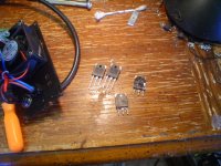
this is what it looks like soldered into the pcb. leave a little short space above the shoulder on the leg so you can bend the legs to allow the transistor be flush against the case and compress the heat sink insulator uniformly in order to spread the heat load out and keep the tab corner from digging into the insulator and cutting through the silicone and shorting the collector to the case.
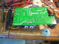
this is what happens when the choke overheats and burns through the trace underneath and short out the hi voltage output of the transformer through the choke to the input of the 12V regulator. the trace runs from the top of those 4 diodes that form the rectifier for the circuit current in the back end. the trace runs right under the choke so when the choke wears through the shellac, actually burns it off, then the hi voltage is carried onto that rectified circuit and you can see where the little 35V cap to the left of the burn that is attached to that trace also is removed because it blew, and the two caps on the output, the 35V and the 100V blew. also the little 35V cap next to that dual op amp also blew ans was removed.
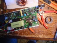
i decided to make my own choke by rewinding the core with larger wire to handle more current without overheating. when i installed it i made sure to add a mica insulator underneath the choke and shellac it in place and mounted the choke higher away from the surface and glued it in place too.

and i added some more conductor from the output of the schottky diodes to the end of the charger to increase current capability.
View attachment 3
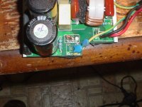
and also i have this picture of where you have to solder the two leads together when you remove the thyristor daughterboard that kinpan has started adding to these chargers to make them 'universal voltage' and can result in damage to the charger when used on 2 wire 240V circuits. which is what happened to cargo tom. but removing the thyristor daughter board by unsoldering the one leg on the right and cutting the other two short allows you to solder the two little stumps of wire together to make the circuit complete to convert it to 120V only. which i do to every kingpan charger i open that have it. not all of them do, just the small ones.
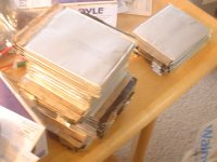
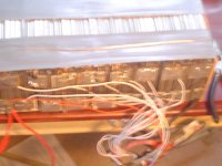
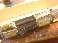
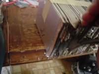
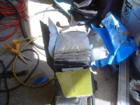
this is the 16S 20Ah ping pack i got from ambrose for parts. it always is the top pouch of the top cell that puffs it seems but this is the bottom, but still on the end where the distortion caused by the tabs being pulled against the subconnector as the pouches expand with age..
the larger kingpan and EMC chargers use a bigger switching transistor format. like the TO-247 package instead of the To-220 package on the smaller chargers. this is 200V 15A. the collector is the tab and middle leg and the emitter is the left leg and base is the right. i just measured the npn transistors on corbins charger and it is 585mV forward bias from base to emitter in the circuit. collector base is about 575 which you would expect because the collector is more heavily doped. since the pn junction in the middle of the transistor doesn't conduct current until the base injects some electrons into the depletion region, then it will measure open circuit on your diode tester. both ways collector-emitter.
on the Sanken C4140 i took out it measures 250mV or 250mR of resistance, so dead, and the other FJP13009 i have here reads 20mR.

this is what it looks like soldered into the pcb. leave a little short space above the shoulder on the leg so you can bend the legs to allow the transistor be flush against the case and compress the heat sink insulator uniformly in order to spread the heat load out and keep the tab corner from digging into the insulator and cutting through the silicone and shorting the collector to the case.

this is what happens when the choke overheats and burns through the trace underneath and short out the hi voltage output of the transformer through the choke to the input of the 12V regulator. the trace runs from the top of those 4 diodes that form the rectifier for the circuit current in the back end. the trace runs right under the choke so when the choke wears through the shellac, actually burns it off, then the hi voltage is carried onto that rectified circuit and you can see where the little 35V cap to the left of the burn that is attached to that trace also is removed because it blew, and the two caps on the output, the 35V and the 100V blew. also the little 35V cap next to that dual op amp also blew ans was removed.

i decided to make my own choke by rewinding the core with larger wire to handle more current without overheating. when i installed it i made sure to add a mica insulator underneath the choke and shellac it in place and mounted the choke higher away from the surface and glued it in place too.

and i added some more conductor from the output of the schottky diodes to the end of the charger to increase current capability.
View attachment 3
and also i have this picture of where you have to solder the two leads together when you remove the thyristor daughterboard that kinpan has started adding to these chargers to make them 'universal voltage' and can result in damage to the charger when used on 2 wire 240V circuits. which is what happened to cargo tom. but removing the thyristor daughter board by unsoldering the one leg on the right and cutting the other two short allows you to solder the two little stumps of wire together to make the circuit complete to convert it to 120V only. which i do to every kingpan charger i open that have it. not all of them do, just the small ones.

this is the 16S 20Ah ping pack i got from ambrose for parts. it always is the top pouch of the top cell that puffs it seems but this is the bottom, but still on the end where the distortion caused by the tabs being pulled against the subconnector as the pouches expand with age..


