Battery Design and Layout...

SlyCayer

100 W
Joined
Sep 6, 2010
Messages
173
Location
Limoges, Ontario
Hi,

I must design a battery pack that will have 39.6V nominal(A123) and 46Ah. Which mean it's either 20P 12S or 12S 20P.

What do you guys suggest I do, am I better with 20P 12S or 12S 20P?

I will have to buy a BMS/Balancer so which setup should cost me less.

I will also be pulling close to 500A on these packs. P.S: I can spot weld tabs directly to a Flat Copper Bar.

My current design is 20P 12S which mean I have 20 cells connected in parallel with a copper flat bar and my design seems to have a flaw as the first cells closer to the connection for series is getting drawn first.

Please help.
 
It's always better to parallel at the cell level, then connect the sub-units into series strings to get the voltage you want. The main advantages are:

- Differences in cell capacity from cell to cell tend to be averaged out, with the series string approach one low capacity cell can cause a string failure without a host of cell level BMS units to prevent it.

- The BMS design is simpler, as you only need to monitor the paralleled cell units. This means 12 BMS channels, whereas the other approach needs 240 BMS channels (assuming you wanted to monitor at the cell level).

There is one potential disadvantage of the large paralleled sub-pack approach; that of a cell going short and taking the whole sub-pack out. In practice this seems to be a very rare thing to happen, it seems that 99.99% of the time cell fail by going to a high resistance condition.

If it were me then I'd build 12 sub-packs made up of 20 paralleled cells and then assemble these sub-packs in series into the main pack.

Jeremy
 
Jeremy Harris said:
In practice this seems to be a very rare thing to happen, it seems that 99.99% of the time cell fail by going to a high resistance condition.

Gee, I wish my packs knew that... I have seen LOTS of cases where a bad cell drew down and killed the whole paralleled string. And if you didn't have some sort of BMS to warn/protect you, that caused the charger to overvolt the remaining cells which then killed the rest of the pack... sometimes slowly, sometime not so slowly.
 
texaspyro said:
I have seen LOTS of cases where a bad cell drew down and killed the whole paralleled string. And if you didn't have some sort of BMS to warn/protect you, that caused the charger to overvolt the remaining cells which then killed the rest of the pack... sometimes slowly, sometime not so slowly.

That's the way to do and Jeremy is right. parallel first and then serie

That is curious, I built alot of packs from recycled/deffective/used lithium packs and it never happened to me.

On every commercial EV cars, battery are made of parallel group first and then all connected in serie.

If you have a bad cell and that it have a leakage current when you build a pack for sure it will drain the rest of cells in parallel... but usually when building a pack you must:

1: test every cells by charging them 100%
2: then leaving them sitting individually for couples of hour to let them stabilize
3: and then measure the voltage of them to ensure NO CELLS HAVE VOLTAGE THAT DROP TOO MUCH. :wink:
4: once you know all cells are ok you can connect them in parallel

It never happened to me to have a working pack that suddenly have a cell becoming weak by itself.

A parallel group can become weak due to overdiacharge and reversal or bad heat management.. but not a single cell since it is connected in parallel so it have the same SOC of every other parallel cells.

I wanted to express my own experience with all these thousands of cells i assembled for me and EV peoples...

Please PAERALLE first and then serie! :wink:

Doc
 
texaspyro said:
Jeremy Harris said:
In practice this seems to be a very rare thing to happen, it seems that 99.99% of the time cell fail by going to a high resistance condition.

Gee, I wish my packs knew that... I have seen LOTS of cases where a bad cell drew down and killed the whole paralleled string. And if you didn't have some sort of BMS to warn/protect you, that caused the charger to overvolt the remaining cells which then killed the rest of the pack... sometimes slowly, sometime not so slowly.

All I can say is that the vast majority of commercial packs are built this way, all the packs I've built have been wired this way and I've yet to see a shorted cell bring a whole sub pack down. That's not to say that it can't happen, but when the alternative (for the OPs application) is to fit a 240 channel BMS I think it's pretty clear which is the better option.

Jeremy
 
SlyCayer said:
n I have 20 cells connected in parallel with a copper flat bar and my design seems to have a flaw as the first cells closer to the connection for series is getting drawn first.

So theres coincidentally a problem with those closer cells?
How do you attach the copper flat bar to the cells? Nickle tabs?
A copper bar - should have virtually zero resistance and let all the cells contribute evenly. If it were really inadequate it could prefer the closest cells but i'd think you wouldn't see it unless you used something lighter than a 14 gauge wire.

Maybe you should move the series connection to a different place and see if the same cells have the problem or if it moves to the cells close to the new series connection?
 
Yes, packs with paralleled cells are unavoidable.

I consider a cell with self-discharge leakage to have a short... perhaps a high-impedance short that drains the parallel group slowly. Whatever, the net effect is that all the cells in that parallel group will die if you do not detect the problem. It is probably the most common failure mode in packs.

I have a couple of A123 cells that failed pretty much dead short. One died while just sitting in a guys pack with with fairly dramatic results (hissing and smoke). It was not charging and had not been abused or damaged. The pack just started spewing.
 
texaspyro said:
I have a couple of A123 cells that failed pretty much dead short. One died while just sitting in a guys pack with with fairly dramatic results (hissing and smoke). It was not charging and had not been abused or damaged. The pack just started spewing.

On the other hand, applications like the 'Killacycle' have hundreds of A123 cells hooked up in big paralleled arrays, abuse the living daylights out of the cells and yet don't seem to suffer problems. They don't even bother to make their packs easy to take apart for repair, as this video show: http://www.youtube.com/watch?v=5vQTBoHPBxQ

Jeremy
 
Killacycles people even weld over the little vent hole.

@ OP

My own build is 1s 10p sub packs, each individually isolated from the next, and then connected in series as Jeremy/DocBass have explained, to bring the voltage up to the required level.

Each Sub-Pack looks like so:
DSCN4606-1.jpg
 
Thank you, Jeremy, Doc and Mighty Volt.

I attached 2 pictures, please let me know the design you would use.

1:
BatteryString1.jpg


2:
BatteryString2.jpg


Also, would you recommend any BMS, cheapest and most reliable? Do I need a BMS or simply a Balancer when charging?
 
The second layout is marginally better in terms of making sure that cell currents are balanced.

You have several choices when it comes to battery management, depending on how much you want to spend, how much time you have to dedicate to looking after the battery pack and how much risk you're prepared to accept.

The least hassle, least time, arguably lowest risk option is to use a BMS that looks after charge and discharge, cutting the pack off if any cell goes too high during charge, or too low during discharge, and ensuring that the cells all remain balanced, with no user input other than plugging the charger is as required. The problem is your high discharge requirement, which pretty much means that your discharge monitor has to be just a warning signal of some kind. This makes fitting an off-the-shelf BMS challenging, as most won't be capable of handling that much current (or anywhere close to it).

Charge balancing is straightforward enough, either using off-the-shelf chargers with built in balancing (many of the RC ones will charge LiFePO4 now) or you could use some of the shunt-type balancers that are around with a bulk charger across the whole pack. The latter solution requires a means to reduce the charge current as soon as the first cell shunt operates, but if you take a look at the BMS thread you should get an idea as to how this works.

You may be best off with a system using the Cellog monitors as the core HVC/LVC detectors. There is a system being put together on the BMS thread that uses these and looks very much as if it might be made to meet your needs.

You could get away with just doing balanced charging and trusting that the pack won't go out of balance in use. This carries some risk, but if you are only going to partially discharge the pack each time that risk might be acceptable. The probability of cells going out of balance is proportional to the depth of discharge when you get down to the last 20% or so of the pack capacity, so the more Ah you take out of the pack, the greater the risk that it'll get unbalanced. You could still hook the pack up to a couple of cheap cell monitors to check cell voltages during discharge, as long as you don't leave them connected when the pack isn't in use (they consume a small, but significant, amount of current when plugged in).

The bottom line is that balanced charging is a must, in my view, but whether you need active, passive or no discharge monitoring/control is really up to you.

Jeremy
 
Hi Jeremy, if I get a BMS to hook up on a relay which can accept 500A draw, wouldn't that work? Even if the BMS is a 20A bms, it would control a "gate" to close and open the battery input/output.

Or even connect a LED light to a bms when the LED light goes off it would mean a sub-pack voltage dropped below the correct voltage.

Could you supply the forum post link of the BMS thread, I just want to make sure I am reading the correct location.
 
You could hook up a big contactor as a cut off fairly readily, there are some nice ones here that only use a small amount of power when activated: http://relays.tycoelectronics.com/datasheets/ev200.pdf

A light, or perhaps a buzzer is another possibility that would work OK.

The BMS thread is a bit big, at around 135 pages, but starts here: http://endless-sphere.com/forums/viewtopic.php?f=14&t=5416 I'd suggest starting at the end of the thread and working forward to find what you want, I'm pretty sure one of the systems that Gary and Richard have worked on should be available somewhere in the last few pages.

Jeremy
 
For even better current distribution, tap the power off the center of the parallel busses. That way only half the average current flows over half the bus resistance. Tapping the power at the ends of the string means the current from the far cells has to flow the full length of the bus bars.

Even even better, series connect the cells along the full length of the paralleled cells. This does make disconnecting paralleled strings for repair or troubleshooting a real pain.
 
texaspyro said:
For even better current distribution, tap the power off the center of the parallel busses. That way only half the average current flows over half the bus resistance. Tapping the power at the ends of the string means the current from the far cells has to flow the full length of the bus bars.

Even even better, series connect the cells along the full length of the paralleled cells. This does make disconnecting paralleled strings for repair or troubleshooting a real pain.

I take your point about the desirability of reducing the length of bus bar that current flows through, but cell balance is, in my view, more important. Surely connecting at opposite ends has exactly balanced current distribution for every cell, doesn't it?

The way I see it is that connecting in the centre means that the bus resistance at the centre of each bus is less than that at the ends. This means that the centre cells will always see a slightly lower bus bar voltage drop than the end cells, so will run at a slightly higher terminal voltage than the end cells when under heavy discharge. The reverse will be true under high charge current conditions.

Connecting at opposite ends evens the voltage drop out so that every cell sees exactly the same bus bar drop, irrespective of where it is in the row.

Jeremy
 
I agree with Jeremy that at least going bus bar inversed will cause the string to have the same resistance from cell 1 to cell 20. It will also make wiring monitor wires better and easier.

Jeremy, should I look for a 24 channel BMS that can take 20A atleast? That way I can charge using the BMS input and discharge using the Contactor? This will cause me to have balancing charging and bms discharging. I will also fabricate a 24channel voltage panel with 24 digital volt meter that every time i plug the charger in I will also have monitor wires going to every string coming out of my packs into a connector.

Let me know what you think of my idea. If you can pitch in with things that might be easier or cheaper, let me know.
 
Jeremy, would this BMS/Balancer work for me? I am read most of the last pages of the thread you provided me and I got that from a conclusion.

http://www.rechargeablelithiumpower.com/oscommerce2/catalog/battery-management-system-board-p-48.html

or

http://www.rechargeablelithiumpower.com/oscommerce2/catalog/battery-management-system-board-p-52.html
 
The BMS doesn't usually limit the charge current during the charge time before the first cell reaches the HVC cut-off, but does after that to keep dissipation down while the pack balances. Gary and Richard are the best people to ask about that BMS, as they are the guys that developed it and know it inside out. I think it's a good solution.

I'm pretty sure that this BMS doesn't handle the discharge current directly, but just provides a low voltage cut-off signal. Again, a quick check with Gary or Richard would seem to be the best bet.

Jeremy
 
Jeremy is right. Our "usual" BMS designs don't use "active cutoff" but lately we have been looking into this. Below is an example. It is a special 4s2p 13.2V/24Ah PSI-based battery that will be used as a 12V SLA replacement battery for a number of applications. What makes it unique is that the whole unit is self-contained, with the only external connections being the brass battery posts. The BMS has an active cutoff circuit that is capable of handling 250-300A peak discharges. There are six large FETs, with very low "on" resistances used in parallel, which are slammed on and off as quickly as possible to reduce the heat generated during transitions.


There are other BMS variants we've looked at for switching relays, etc., but I think it's probably not a great idea to be cycling power on and off, and then on again, if there are 500A loads present. In the BMS for the battery above, we have hysteresis and delays built-in, and we have 6 more of the same big FETs that are used as diodes so that the whole battery is bypassed, if a channel's LVC trips. One application these will be used in is for powering a GEM EV, which is basically an over-sized, "street-legal" golf cart. Six of these will be used in series so if the LVC trips in one battery, it is cutoff, and bypassed, so that the voltage doesn't suddenly go to zero, but is reduced by the voltage of one battery.

I still like the idea of pulling down on the throttle signal, or tripping an ebrake input, for most applications, rather than cycling power on the whole system.

-- Gary
 
Thank you clarifying.

You do not suggest I use your system as LVC/Balancing Unit, even with a contactor/relay? I undetstand what you mean by the LVC would go back on and off on and off and that is a problem. But don't you think we could find a way to have a switch that is moved from on to off at the same time that must be put back to on before the Contactor/Relay is turned on again? Something like a Magnetic Toggle switch which can be put on by the user and then as soon as the power is lost, the toggle goes back to off and must be manually put back to on?

If you do not suggest your system, which one could work for me?

Could this one work? http://www.batteryspace.com/batterymanagementsystemmastermoduleforlifepo4batterypackupto77v500arated.aspx

It's a lot of money, If you can find a cheaper solution, please, please let me know.
 
SlyCayer said:
Thank you clarifying.

You do not suggest I use your system as LVC/Balancing Unit, even with a contactor/relay? I undetstand what you mean by the LVC would go back on and off on and off and that is a problem. But don't you think we could find a way to have a switch that is moved from on to off at the same time that must be put back to on before the Contactor/Relay is turned on again? Something like a Magnetic Toggle switch which can be put on by the user and then as soon as the power is lost, the toggle goes back to off and must be manually put back to on?

Yes, you could drive a contactor easy enough, and you could probably do some sort of latching setup that has to be reset, but think about the situation where your pack is close to the end of capacity and you are starting off from a stop. Do you really want to have it cutout completely while you are stuck in the middle of an intersection? The way our normal LVC function is used with most typical setups is that when a cell's LVC trips it is like pressing a momentary pushbutton. As soon as the load is removed, the cell's voltage will always recover back up close to the nominal voltage. When it does, it releases this "pushbutton". In reality, these are really pushbuttons, but optocoupled electronic switches. All of these opto switches are wired in parallel so that any one LVC circuit can "turn on this "switch". Anyway, this combined switch is tied to either a dedicated brake input on the controller, or to the throttle signal itself. Basically, what happens is that throttle signal is temporarily cutoff, by grounding it, for as long as the LVC is tripped. This removes the load on the cell. It usually takes about 1/2-to-1 second for the cell voltage to recover and then the pull-down of the throttle is released. If you keep on the throttle, it will "hit" again, and the cycle repeats. This happens at roughly a 1-2Hz rate, and it definitely gets your attention. Usually, if you back off the throttle a bit, it will reduce the load enough to allow you to continue on at a reduced power level. In most cases, with the chosen LVC set points, you can have as much as 10% capacity left at the time the first cell hits the LVC point. At the end of capacity, even the slightest throttle will cause the 1-2Hz oscillation.

My point is that given the way individual cell LVC circuits work, you probably don't want to be cycling a main power contactor at a 1-2Hz rate. :roll: You also don't want to simply kill power, that then needs some sort of reset procedure, at the first LVC "hit". For larger EVs, I think a nice, loud, audible alert is probably a better idea. Another possibility is maybe reducing the throttle 50%, instead of pulling it all the way off.

-- Gary
 
I would be better off with a audible alert or light would work great.

I am using a Alltrax controller 7245.

I know my controller is controlled by a foot pedal going from 0-5K ohms, so maybe I could get a resistor and 2 relays to create a "half" throttle?

You've been great help, I think I will probably use your BMS with a audible alert and LED Warning light. What do you think?
 
SlyCayer said:
I would be better off with a audible alert or light would work great.

I am using a Alltrax controller 7245.

I know my controller is controlled by a foot pedal going from 0-5K ohms, so maybe I could get a resistor and 2 relays to create a "half" throttle?

You've been great help, I think I will probably use your BMS with a audible alert and LED Warning light. What do you think?

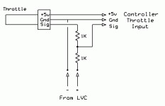
The "half-throttle" implementation is pretty easy. The following should give you roughly 50% when the LVC hits:

LVC 50% Throttle Interface.gif
 
Back
Top