Condor PSU Help

steveo

100 kW
Joined
Oct 6, 2007
Messages
1,786
Location
Woodbridge, Ontario
Hey Everyone,

I picked up some nice condor 250w 48v passive cooling psu a while back that have PFC

I've custom made a cover for the cases to include a fan with each psu!

the psu have one pot in the middle to control current .. and one pot on the dc output side for voltage..

they also have voltage sence wires that can be added


**

so .. i would like to use 2 of these psus in series for 88.8v to charge my 24s 4p a123 battery on my bike...

however i run into the issue that the psu go into an over current or saftey mode and don't deliver constant dc current ... they will fluctuate and not work properly...

I ran a test with one 48v psu on my cba 2 ... and it worked perfectly

if i attach a hair dyer as a load ... it will also deliver a steady current at about 4.5amps...


I've don't a video attached here http://www.youtube.com/watch?v=fcsHZJtc_Ac

[youtube]fcsHZJtc_Ac[/youtube]


showing .. the issue i'm having ... i'd appreciate your help on solving the issue .. if you listen closly in the video ... you can actually hear the psu ... clicking .. when connected to battery ... and the turnigy metter jumping everywhere current wise...

thanks in advance..

-steveo
 
I'd guess the overcurrent limiting is the type that just shuts off the output. When you attach the pack, it's probably trying to draw more than the current limit and causing it to drop out.

If you lowered the output voltage so it's just a little over the pack voltage, it should run. You could slowly dial up the voltage until it reaches the rated current, then keep cranking it slowly up as the pack charges. This would at least test whether this is the problem or not.

The little Meanwell current limiters I'm building might work with that power supply. The trick will be to find the tie in point. Look at the 16pin DIP on the board and see what the number is. You can usually trace back the lines from the voltage adjusting pot to find the voltage sensing input.
 
fechter said:
I'd guess the overcurrent limiting is the type that just shuts off the output. When you attach the pack, it's probably trying to draw more than the current limit and causing it to drop out.

If you lowered the output voltage so it's just a little over the pack voltage, it should run. You could slowly dial up the voltage until it reaches the rated current, then keep cranking it slowly up as the pack charges. This would at least test whether this is the problem or not.

The little Meanwell current limiters I'm building might work with that power supply. The trick will be to find the tie in point. Look at the 16pin DIP on the board and see what the number is. You can usually trace back the lines from the voltage adjusting pot to find the voltage sensing input.

hey Fechter,

When you refer to 16 pin dip what exactly do you mean?... There is a 14 pin chip near the voltage pot ... it reads

lm339n
Gk5290J5

and theres these letters on certain pins on the chip.. (i think this is what your looking for..)VB , GK, (CHN -- might belong to a pin .. not sure)

datasheet here:

http://pdf1.alldatasheet.com/datasheet-pdf/view/53572/FAIRCHILD/LM339N.html

i'm gona check the trace that runs to the chip ...

** And yes.. your absolutly right ... when the voltage is say within a volt or 2 of the battery the psu will run ... if its like a 5v gap... it starts cutting out**

i tested approx 3-3.5v max adjustability before the protection kicks in on the psu...

my bike fully charged is 88.8v .... my pack is at 79v ... so 8v difference... and 2 psu's in series only like 7v difference .

i guess what we are trying to acomplish is to trick what voltage the chip is reading vs what the actually voltage is..


update** after checking things...

ok .. there is a ground on the pot that runs through 2 resistors & then to the chip (PIN 4)

i'm not sure on where the + sence is ... that jumper on the end of the board has both + sence & - Sence

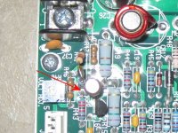
some photos... attached

-steveo
 

Attachments

  • IMG_7551[1].jpg
    IMG_7551[1].jpg
    224.1 KB · Views: 621
  • IMG_7552[1].jpg
    IMG_7552[1].jpg
    413.5 KB · Views: 621
It's a little hard to trace out from the pic due to the angle. See if you can get a picture more straight on to the board.
I find it useful to put some paper over the flash to reduce the reflection. The 339 is a quad op-amp, which is most likely the part sensing the voltage.

Also, there's a transistor looking thing near the voltage adjuster labeled U2. See if you can read the number off that one. I'd guess it's a 431.
 
fechter said:
It's a little hard to trace out from the pic due to the angle. See if you can get a picture more straight on to the board.
I find it useful to put some paper over the flash to reduce the reflection. The 339 is a quad op-amp, which is most likely the part sensing the voltage.

Also, there's a transistor looking thing near the voltage adjuster labeled U2. See if you can read the number off that one. I'd guess it's a 431.


i will get that info for you asap...

i managed to change a resistor (blue colour)... top right of the voltage pot originaly 1.10kohm... i put 1.230ohms .. and it gives me voltage adustment from 35v - 43v..

i still haven't managed to get the psu to not go into over protection i series 2 psus at 84v ... with pack voltage at 79v .. and it cuts out still gahh..

i'll report back with the missing info..

**update**

u2 is TL431.. You are correct :)

I've attached some better photos

-steveo
 

Attachments

  • IMG_7561[1].jpg
    IMG_7561[1].jpg
    281.9 KB · Views: 589
  • IMG_7559[1].jpg
    3.1 MB · Views: 588
bump... :roll:
 
Good pictures.

If you turn on the supply and measure the spot indicated, it should be right around 2.5v. This would be the spot to attach the voltage sensing line from the Mini Meanwell limiter.

If the voltage measures around 2.5v, the Meanwell limiter circuit should work.

Condor PS voltage sense.jpg

My next batch of limiter boards has shipped, so should be here soon. It's pretty easy to make your own on a perf board.
 
fechter said:
Good pictures.

If you turn on the supply and measure the spot indicated, it should be right around 2.5v. This would be the spot to attach the voltage sensing line from the Mini Meanwell limiter.

If the voltage measures around 2.5v, the Meanwell limiter circuit should work.


My next batch of limiter boards has shipped, so should be here soon. It's pretty easy to make your own on a perf board.

thanks for your help fechter...

i'll check it out tonight :) if it works i'll let you know how many boards i need...

-steveo
 
fechter said:
Good pictures.

If you turn on the supply and measure the spot indicated, it should be right around 2.5v. This would be the spot to attach the voltage sensing line from the Mini Meanwell limiter.

If the voltage measures around 2.5v, the Meanwell limiter circuit should work.


My next batch of limiter boards has shipped, so should be here soon. It's pretty easy to make your own on a perf board.


Hey Fechter,

It measures 2.5v

:mrgreen:

i will be needing a few of your boards.. ... i shoot you a quick pm.

thanks alot for your help ... I really appreciate your knowledge to solving this issue!

-steveo
 
Yes, that's a good sign.

Another fun test would be to turn on the supply and measure the voltage. While running, place a ~10k or so resistor from that sense point to the positive output terminal and see what it does to the voltage. If it's like the Meanwell, the voltage will drop quite a bit, like half normal.
 
Hey Fechter

just wanted to let you know the voltage sense boards worked!

i charged my bike with my batts at 50% soc with 2 psu's in series and it worked!

i will try to charge with a dead battery to see if the protection cut off kicks in ..

the pot is very sensitive .. if i adjust it to high or to low ... it goes into protection .. ... but i assume thats normal..

i gotta put better cooling ... the psus get burning hot with the little 1" fan i put LOL....

-steveo
 
OK, good to know.

If you turn the current limit down enough, you can reduce the amount of heating.
 
Back
Top