Convert Laser pointer - 2 aaa alkaline to single 18650 A123?

MitchJi

10 MW
Joined
Jun 2, 2008
Messages
3,246
Location
Marin County California
Hi,

I frequently need to use one of these Galaxy (multiple beams) Laser Pointers:
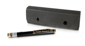
GalaxyLaser.png
The reason I want to use a larger battery is that, the Laser Pointers work well with fresh alkaline cells at 1.62v. But when the cells get to about 1.48v Laser Pointers only work well for about 20-30 seconds, then get very, very dim. Since the nominal voltage of the alkaline cells is 1.5v and the Lasers draw about 30mW I think that's after about 20 minutes of use. I really don't like the combination of short life and non-rechargeable batteries so I'd like to use it with a single A123 18650 cell.

I got the following from the manufacturer:
Normally Green laser pointer designed for operation voltage 2.8~3.2V...

My engineer do confirm that our Green laser pointer can’t be allowed to use voltage >3.3V, it may damage our pointer.
My tentative plan is to (unless someone chimes in with a better idea):

1. Buy one of these for a cell holder (probably overkill - but I want the cell enclosed and I can get an LED module and end up with a flashlight Laser pointer combo):
http://www.lighthound.com/Solar-For...650--L2P-Host-HA-III-Black-Finish_p_3473.html
Your Price: $22.99
NOTE: This is NOT a complete flashlight. There is no bulb or batteries.

Features:
-Special edition of Solar Force L2 Host in Mil-spec type III hard anodized in black

Features:
* Flashlight host (head assembly + battery tube + tail switch assembly) without built/drop-in
* Made of aluminum alloy
* Uses both primary (CR123A) lithium or rechargeable li-ion (16340 or 18650) batteries (not included)
* Tail clicky switch
* Length x diameter (head and battery tube, mm): 140 x 32 x 25
2. Use a wood dowel in the laser pointer the length and diameter of 2aaa's with wires on the ends, going through a small hole I'll drill in the end cap.
3. Wires will go to the end of the 18650 in the Solar Force L2 Host.
4. Use a Voltsphreak 2 amp charger to charge single (or 2 in parallel) A123 18650's.
5. Run the flashlight for a few seconds before using the laser pointer to get the cell down to 3.3v.

If you think you have a better idea (for the whole project or a individual part of it) please post it.

Thanks!
 
I would use a Zener diode to regulate the voltage, instead of relying on a light to pull the voltage down. Lithium has such a flat discharge curve that you'll ear a sizable chunk of the battery before you get it into the safe zone, since nominal is 3.3v already. And even fully charged, its only 1100mAh. A rechargable AA is something like 2700mAh (found here, for example http://www.amazon.com/Sanyo-NiMH-Rechargeable-Batteries-4-Pack/dp/B000IV413S)
non rechargable batteries usualy have a higher capacity than that.

So while its an awesome idea, its going backwards on capacity by a lot.
 
Hi,

Drunkskunk said:
I would use a Zener diode to regulate the voltage, instead of relying on a light to pull the voltage down.
I don't know how to do that and I think its will be to difficult.

Drunkskunk said:
Lithium has such a flat discharge curve that you'll ear a sizable chunk of the battery before you get it into the safe zone, since nominal is 3.3v already. And even fully charged, its only 1100mAh.
But maybe I'm wrong. I thought Gary said that A123 cells dropped to nominal which is where I need it to be very quickly but he didn't say that exactly (although he does say there is a very quick drop in v):
http://www.endless-sphere.com/forums/viewtopic.php?f=14&t=2498&p=80038#p80038
GGoodrum said:
That means you check the cell voltages not right after charging, but after they've been put under some sort of load for 10-30 seconds. That will give you a more accurate indication of its "full" voltage. This will usually be a number somewhere around 3.5V. Fresh off the charger what you see is a surface charge that builds up on the electrodes. This number can vary quite a bit for various cells, even for cells that are closely matched in capacity. Putting a load on the cells briefly, will burn off this surface charge.

With a123s, abusing them will cause the cells to loose about 10% of their capacity. The easiest way to tell is that within a minute, or two, the surface charge will burn off by itself, and the voltage will only be around 3.35-3.40V
Drunkskunk said:
A rechargeable AA is something like 2700mAh (found here, for example http://www.amazon.com/Sanyo-NiMH-Rechargeable-Batteries-4-Pack/dp/B000IV413S)
non rechargeable batteries usually have a higher capacity than that.

So while its an awesome idea, its going backwards on capacity by a lot.
I got excited when I thought all I need to do to get the capacity I need is put 2 rechargeable alkaline cells in the laser pointer, then I realized you posted the capacity for AA (double A) and the laser pointer takes AAA (triple A) and they are NIMH. I already tried using two triple a NIMH and its nice to be able to recharge them but the nominal voltage is so low the capacity is much less.

Thanks for the heads up on the capacity and the idea though. I think I'll plan for dual 18650's in parallel if the single doesn't do it.
 
Hi,
Drunkskunk said:
I would use a Zener diode to regulate the voltage, instead of relying on a light to pull the voltage down.
MitchJi said:
I don't know how to do that and I think its will be too difficult.
:oops: Sounds like the perfect solution if its not to difficult or expensive. Anyone willing to tell me how to do it?
 
I'll have to read Gary's post again, but an A123 cell is higher than the safe range of the Laser.
Discharge chart if you want it.
http://www.uvm.edu/~kgallo/Images/Discharge Characteristics graph at 25 deg.jpg

The regulator is just a zener diode basicly shorting the circuit, with a resistor in to keep it in the range you need. Looks like this:
zener-diode-voltage-regulator.gif


And that image comes from a site with a calculator to tell you what value parts you need. Just put in the max Miliwatts you want to run the Laser at, and the voltage in, and what you want to get out. (3.2 volt should be good)

http://www.reuk.co.uk/Zener-Diode-Voltage-Regulator.htm

I missed that it was tripple A, sorry. I was quoting double A.
 
Hi,

Thanks for the chart. Under a 1A (~ .4c) load when it hits 3.3v its still got about 90% of its capacity.

Drunkskunk said:
I'll have to read Gary's post again, but an A123 cell is higher than the safe range of the Laser.
Discharge chart if you want it.
Discharge%20Characteristics%20graph%20at%2025%20deg.jpg


The regulator is just a zener diode basically shorting the circuit, with a resistor in to keep it in the range you need. Looks like this:
zener-diode-voltage-regulator.gif


And that image comes from a site with a calculator to tell you what value parts you need. Just put in the max Miliwatts you want to run the Laser at, and the voltage in, and what you want to get out. (3.2 volt should be good)

http://www.reuk.co.uk/Zener-Diode-Voltage-Regulator.htm
And thanks for the zener diode info!

Houston, we have a problem:
As long as the input voltage is a few volts more than the desired output voltage, the voltage across the zener diode will be stable.
Enter the values for Vout (the desired output voltage - equal to the zener voltage of your diode), Vsource (the maximum power supply voltage - must be at least 2-3 Volts higher than the desired output voltage), and Imax (the maximum current which will be drawn by the load plus a 10% safety buffer).

EDIT I think its ok (a lower voltage is ok).
12 volts is sufficiently above 8 volts to ensure that any ripples in the supply will not take us below our target voltage.
 
Hi Richard,

Thanks, sounds like an excellent solution.
fechter said:
I'd suggest a low dropout linear regulator chip. Something like this one:
http://ww1.microchip.com/downloads/en/DeviceDoc/21373b.pdf
(available from Mouser).
Its very easy to hook up, just input, output and ground. This one has a fixed 3.3v output.

Do you know how much current the pointer takes?
"Max < 30mW".

Normally Green laser pointer designed for operation voltage 2.8~3.2V...

My engineer do confirm that our Green laser pointer can’t be allowed to use voltage > 3.3V, it may damage our pointer.
I'm pretty sure 3.3v will be fine but thats right at the limit and I don't want to chance blowing a $200 Laser Pointer so maybe I should go with the 3.0v unit?

Thanks Again!
 
I think 30mW is the output. Input will be much more, but I suspect less than 500mA. It would be best to try measuring the battery current.

I think they make a 3.0V unit. There are others that can be made adjustable with a pot.
The regulator chip might need a heat sink depending on the actual current.
 
Hi Richard,

fechter said:
I think 30mW is the output. Input will be much more, but I suspect less than 500mA. It would be best to try measuring the battery current.
Thanks for pointing that out! Looks like it will work though. From the spec sheet (no surprise that 2 AAA's don't last very long):
GreenLaserSpecs.png
fechter said:
I think they make a 3.0V unit. There are others that can be made adjustable with a pot.
The regulator chip might need a heat sink depending on the actual current.
They do make a 3.0V unit but no 3.2V unit is listed.

With a maximum 500mW draw do you know if it will need a heat sink? Any idea how big it would need to be and how much ventilation will be required?

Current plan is to put the cell in one of these:
sku_100999_1.jpg


And to carry the cell and laser pointer in a soft case, which might not work well with a heat sink.

I think first I'll hook it up and use a flashlight to drain the cell down to just under 3.3v and then integrate the chip when I have that working.
 
Good guess eh?

Going from 4v to 3v @ 500mA would be 500mW of dissipation. At TO-220 package can dissipate that much without a heat sink. Still, it would be good practice to have some kind of thermal path from the regulator to the case. My guess is the pointer doesn't stay on for really long periods of time so heating should not be a problem. Inside a soft case, I'd suggest using a piece of sheet aluminum for a heat sink. Something like 1"x2" should be more than enough. You can always run it for a few minutes and see how hot it gets. These regulators are thermally limited, so it will shut down if it tries to get too hot.
 
Hi,

fechter said:
Good guess eh?...
Thanks!

Success! I'm very pleased. It has a much longer run time and its rechargeable :).
GalaxyHack1.jpg

GalaxyHack3.jpg


OTOH dogman was correct in that getting an A123 Cell down to 3.3V uses (I think) about 40% of the capacity of the Cell and the light starts to sag when the Cell hits 3.23V :shock:.

But it lasts so much longer that, as is, its a very big improvement.

Next I plan to use one of these aluminum Cell Holders. Its designed to accommodate a 3.5mm DC power plug:
18650 Battery Holder / Charger Tube
18650 Battery Holder / Charger Tube LIH-18

This is an aluminum battery holder for Li-Ion 18650 batteries that doubles up as a charger tube.

The ventilated aluminum holder tube will protect your spare battery from getting damaged...

As the Holder / Charger tube double functions as a separate charger bay, you can connect the 4,2V DC 3,5mm charger pin from the power adapter directly into the Holder.
SecuriLed%20Battey%20Holder.jpg

battery-tube-connected.jpg
The optimum solution (which I plan to do once I have the better Cell Holder) is to use the 3.3v version of the chip recommended by Richard (thanks again!):
VoltageRegulation.png


Planning on using it with something like one of these protected 3100mah 3.6v nominal Panasonic Cells (maybe something cheaper, a $13 cell with 3100mah is probably overkill ). Using the chip with a protected Cell will make charging and using it plug-and-play and the 3100mah capacity will give me a huge run time:
http://www.cobbcarpet.com/sanyo.html
Panasonic 3100mah #18650 Lithium-Ion Cells
Low Internal Resistance Cells (55mOhms) for Boost Drivers
Nominal Capacity: Typical 3100 mAh
Discharge Current: Maximum 6200mA
Charging Voltage: 4.2VDC
Charging Time: 2-3 hrs depending on depth of discharge
Size: Max. 18.25 x 65 mm - Weight: 48g
Charge : 0°C to +40°C - Discharge: -20°C to +60°C
Circuit Interruption Protection - Short; Overcharge; Excessive Temp - Mechanical Thermal Protection,
Safety - Cell Certified by UL Standard UL-1642;
New Heat Resistance Layer prevents overheating

One more question:
If I mount the chip on a piece of Aluminum which will be the ground for the chip and the 2 capacitors does it need to be electrically connected to either or both the Cell Holder and the laser pointer?
 
Back
Top