YoshiMoshi
10 W
I'm simply trying to understand how to select nickel strip for my battery pack. Note that I'm just simply trying to understand the math here only and the concepts behind selecting nickel strips, and nothing more. I'm not suggesting anyone do anything unsafe.
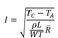
I'm building a 5S3P Li-Ion pack from 21700 cells. I have found various charts and tables depicting nickel stirp dimensions and their acceptable currents. But I'm not sure where these values come from. An example of one is below.
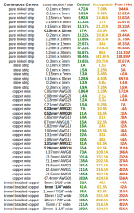
I'm trying to minimize the thickness of my nickel strips, by evaluating how wide I can make my strips. Typical cheap spot welders have difficulty spot welding strips thicker than 0.15 mm. The largest cross sectional area on this chart is 12 mm wide and 0.15 mm thick, with optimal current carrying capacity of 17 A (from that table).
My BMS has a continuous discharge current of 40 A, and a maximum instantaneous current of 80 A. Do I select nickel strip for 40 A instead of 80 A? I would assume so. So lets assume 14 mm thick and 50 mm long (3 series connections of
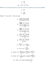
Bulk resistivity of pure nickel is 6.99 x 10^(-8) ohm meters
Strip is 14 mm by 0.15 mm by 50 mm, current stated at 40 A
Resistance is length / (width * thickness) * bulk resistivity
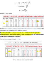
( ( 50 mm ) / (14 mm * 0.15 mm) )( 6.99 * 10^(-8) ohm m)( 10^3 mm/m) ~ 0.001664 ohm
Power is I squred R or (40 A)^2 * ( 0.001664 ohm ) ~ 2.663 W
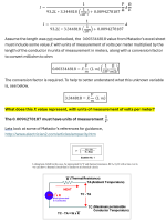
Voltage across strip is I * R or ( 40 A )( 0.001664 mohm )= 0.0666 V
So pased on a loss of 2.663 W from the nickel strip is 4 mm by 0.15 mm by 50 mm considered optimal to carry 40 A? I'm not exactly sure how much power loss is considered "optimal" "acceptable" or "poor".
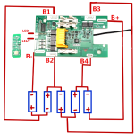
Additionally, I was wondering how much current should I consider for the balance leads coming off the BMS? Meaning B1, B2, B3 and B4 below.
Thank you for any help in understanding this!
I'm building a 5S3P Li-Ion pack from 21700 cells. I have found various charts and tables depicting nickel stirp dimensions and their acceptable currents. But I'm not sure where these values come from. An example of one is below.

I'm trying to minimize the thickness of my nickel strips, by evaluating how wide I can make my strips. Typical cheap spot welders have difficulty spot welding strips thicker than 0.15 mm. The largest cross sectional area on this chart is 12 mm wide and 0.15 mm thick, with optimal current carrying capacity of 17 A (from that table).
My BMS has a continuous discharge current of 40 A, and a maximum instantaneous current of 80 A. Do I select nickel strip for 40 A instead of 80 A? I would assume so. So lets assume 14 mm thick and 50 mm long (3 series connections of
Bulk resistivity of pure nickel is 6.99 x 10^(-8) ohm meters
Strip is 14 mm by 0.15 mm by 50 mm, current stated at 40 A
Resistance is length / (width * thickness) * bulk resistivity
( ( 50 mm ) / (14 mm * 0.15 mm) )( 6.99 * 10^(-8) ohm m)( 10^3 mm/m) ~ 0.001664 ohm
Power is I squred R or (40 A)^2 * ( 0.001664 ohm ) ~ 2.663 W
Voltage across strip is I * R or ( 40 A )( 0.001664 mohm )= 0.0666 V
So pased on a loss of 2.663 W from the nickel strip is 4 mm by 0.15 mm by 50 mm considered optimal to carry 40 A? I'm not exactly sure how much power loss is considered "optimal" "acceptable" or "poor".
Additionally, I was wondering how much current should I consider for the balance leads coming off the BMS? Meaning B1, B2, B3 and B4 below.

Thank you for any help in understanding this!


