
You are using an out of date browser. It may not display this or other websites correctly.
You should upgrade or use an alternative browser.
You should upgrade or use an alternative browser.
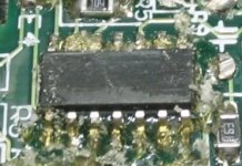
Currie/Ananda controller guts
- Thread starter TylerDurden
- Start date


TylerDurden
100 GW

TylerDurden
100 GW

BiGH
100 kW
would i be right in assuming the reason they fill this with resin is to
a: dissipate heat to the metal controller surface
and
b: provide water resistance
(but mostly B)
??
a: dissipate heat to the metal controller surface
and
b: provide water resistance
(but mostly B)
??
TylerDurden
100 GW
Methinks the potting is to reduce infiltration by moisture, contamination and curious hackers looking to overvolt their e-bikes.
8)
8)
Reid Welch
1 MW
Water protection mostly, I think. It's a clear compound--if they were wanting to make it hard for us, they'd make it opague, right?
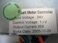
Well, this is identical to my Currie's controller.
Now I understand why it does not object to 42V.
Q: If there is a simple way to readjust the controller to output 25A max,
someone please let me know?
I have been trying since last February to get a 36V 25A (CR36V450) controller from Currie. They take the order, "it's on the way" and nothing ever comes because they never send it out. The losers. Well, one is -supposed- to ship out next week to me (again).
I don't know if it'll come, and I don't know that it'll fit in the existing controller cubby.
Tyler, your revelation of the controller's guts are most helpful here.
I can see/we can see just how relatively simple, efficient and unstressed the parts can be in a brush motor controller.
No wonder these don't often fail.
The company behind the controller makes high quality goods.
It's a well-engineered controller, and must be, for Currie's mass market needs.
If I could unpot mine and make some circuit adjustment to cut down the current, that's the best I can hope for.
Why? To save battery juice. I don't need 35A at 37 or 42V.
The bike runs on a fresh LiPo charge 27mph, drawing 18 to 20A on level road, no wind.
And that's all I need: 25A, ideal here.
I never would've thought to mess with that rubbery potting compound if not for your intrepidness.Thank you Tyler!
TylerDurden
100 GW
Methinks they're just too cheap to pay for the pigment...Reid Welch said:if they were wanting to make it hard for us, they'd make it opague, right?
Reid Welch said:I never would've thought to mess with that rubbery potting compound if not for your intrepidness.
LOL... I seem to remember somebody (REID) reminding the group that epoxy softens significantly when heated...
It is funky stuff... it is rubbery and crumbly... the fun part is to try to get it to peel-away cleanly.
Reid Welch said:Q: If there is a simple way to readjust the controller to output 25A max, someone please let me know?
The shunts are in the center. you may be able to replace them with a wire/switch setup like 29a is configuring for current limiting (?):
http://endless-sphere.com/forums/viewtopic.php?t=800

Attachments

Reid Welch
1 MW
Yes, that's my old advice: all epoxies come apart with heat, and not that much heat is needed: usually under 200F turns them temporarily into cheese.
That clear stuff is a rubbery epoxy then-not hard to start with (I prodded mine).
So! Those "shunts", are these the famous "buzz bars" I have heard about?
What's the way to adjust them? for more or for less conductivity to reduce current.
I don't know how things work. I do know cheezed epoxy and dental picks.
Say ahhhhhh, Controller. Say "ahhhhhhh" now.... :lol:
Thank you Mr. President Tyler and Tippecanoe too.
_______________
edit: Found a tutorial created by an e-s member. Woo-ooot!
http://www.users.bigpond.com/solarbbq/controllersintro.htm
Hmmm...if this is the case then I should remove only the potting around the buzz bars
with an abrasive rubber wheel on the Dremel tool remove metal from the span of one or both bars until results are gained.
edit:
Thanks
That clear stuff is a rubbery epoxy then-not hard to start with (I prodded mine).
So! Those "shunts", are these the famous "buzz bars" I have heard about?
What's the way to adjust them? for more or for less conductivity to reduce current.
I don't know how things work. I do know cheezed epoxy and dental picks.
Say ahhhhhh, Controller. Say "ahhhhhhh" now.... :lol:
Thank you Mr. President Tyler and Tippecanoe too.
_______________
edit: Found a tutorial created by an e-s member. Woo-ooot!
http://www.users.bigpond.com/solarbbq/controllersintro.htm
...Max. current can be adjusted by adding taking away solder from buzz bar (or by other suitable method).
Have done some experiments with this;
current can be reduced to any value by increasing resistance across buzz bar.
Conversely, decreasing resistance of buzz bar the max. amps can be increased........a lot!...
Hmmm...if this is the case then I should remove only the potting around the buzz bars
with an abrasive rubber wheel on the Dremel tool remove metal from the span of one or both bars until results are gained.
edit:
OK, Tyler, I've read that now and so because of you, I know what to do.The shunts are in the center. you may be able to replace them with a wire/switch setup like 29a is configuring for current limiting (?):
http://endless-sphere.com/forums/viewtopic.php?t=800
Thanks
TylerDurden
100 GW
Reid Welch said:...if this is the case then I should remove only the potting around the buzz bars with an abrasive rubber wheel on the Dremel tool polish off a bit of metal from the span of one of the bars until results are gained. Is this a sound plan, folks?
Methinks you won't have the ability to go back... 8)
I might consider lifting one end of a shunt and add some 10ga wire in series, being careful to not short against anything.
I haven't spec'd trimmer pots in decades... they may be overkill. (The emperor may have some tips.)
:?
Reid Welch
1 MW
Yeah, but we're talking about a milliohm of resistance in that bar.
Need only a one-time adjustment.
I'd do it this way: When the bike is back together, running and all,
I'll excavate the bars. Grind off a bit of the metal, make full throttle stall test for a second.
Then grind more until the Drain Brain indicates max current of 25A at full stall.
This way I don't disturb the board or make new joints.
And it will take only a few trials to get it just right.
TylerDurden
100 GW
Go for it! Controllers are fairly cheap...
...if you can get those rope-smoking numbnutz to ever send em to ya.
...if you can get those rope-smoking numbnutz to ever send em to ya.
Doctorbass
100 GW
Reid,
To change the limiting current of that controller shunt, there is a simple and more safe way. As you know, that shunt produce a low voltage across the lead when current pass thru it. that voltage is probably the signal used to indicate the limit to some comparator chip. ex: 35A= 10mV
25A=7mV. What you need is to find and modify the resistor that divide that voltage before to go to the comparator chip input.
Normally, some PWM chip have an input that is controlled by one of these comparator chip. that chip have 2 input. one IS the reference voltage input and the other, the sens input(inverting and non inverting)(like the one from the shunt mV output). Probably, the reference voltage is made from 2 resistors in series between a voltage reference(supplied by one of the pins of the PWMchip) and the ground. This voltage divider(or a simple potentiometer) set the voltage ref that the sens need to be compared with.
In other words, just fins some resistor or a pot near the PWN chip and connected close to the shunt and jump one of those with a 10k while you run that controller and see if the limite change. See the tl497 pwn IC.. better than the 494.. the 497 include a current limit sens input.http://www.ee.washington.edu/stores/DataSheets/voltreg/tl497.pdf
I know my explanation would probably need to be read few time to be understod correctly, ... anyway.. it's the end of the week.. a looong week for me.. hope you'll understand something... :lol:
Doc :|
I've discovered where the little resistors are in a Crystallyte controller, but tracing out that one to find which resistor will adjust the limit will take some time and probing.
Nice job on digging out the potting. It's much harder than it looks in most cases.
Grinding away on the shunt wire is a tough way to do it.
Just snip the top one and see what it gets you. Should be about 18 amps.
After snipping, you could solder some copper wire to the snipped ends and run it to a switch if you wanted to switch it.
If you use something like 14 ga wire to bridge the snip, you could wind up a foot or so and stuff it in the case. Adjust limit by changing length of wire.
Ypedal
100 TW
Hm.. i wonder how difficult it would be to Un-pot a kollmogen... i have one that is about to get turfed.. so good chance to experiment.
If i took the Heat-Gun to it.. would that do the job? I have the dental picks.. and a 6 pack of beer.. should be golden.. now.. gotta remember to only drink the beer once i'm done..
If i took the Heat-Gun to it.. would that do the job? I have the dental picks.. and a 6 pack of beer.. should be golden.. now.. gotta remember to only drink the beer once i'm done..
TylerDurden
100 GW


Hmm.. Quite a bit different to the controller in my I-Zip.. Mine has exactly the same 24V/35A paper sticker on it, but on the other side, there's a tiny label that says Ace Bike, China, and is *NOT* potted at all, just a caset metal box with a gasket and the lid screwed on.. I've only got 3 MOSFETs in my controller, and there's a big relay right in the middle of the circuit board..
jateureka
10 kW
Sorry to bring up an old thread, but I have a blown 36V15A Ananda controller and found this a good read for how to get the potting out.
If anyone is interested, this guy ran his 24V15A controller at 36V and has some test data. http://www.bikeforums.net/archive/index.php/t-323269.html
One thing that may have been overlooked though is that the controller low voltage cut-off will be too low to protect the 36V batteries from over discharge.
TylerDurden
100 GW
jateureka
10 kW
More info on 3615 BLDC controller in this thread http://endless-sphere.com/forums/viewtopic.php?f=2&t=2332&p=469470#p469470
The Mighty Volt
1 MW
Reid Welch said:Yeah, but we're talking about a milliohm of resistance in that bar.
Need only a one-time adjustment.
I'd do it this way: When the bike is back together, running and all,
I'll excavate the bars. Grind off a bit of the metal, make full throttle stall test for a second.
Then grind more until the Drain Brain indicates max current of 25A at full stall.
This way I don't disturb the board or make new joints.
And it will take only a few trials to get it just right.
My full-stall with that controller and a 24v geared motor right now is 15.X Amps. Pretty weak, no? I am going to try that controller with 40v and see how I get on. Ap won't be any higher but still....I'd like to see what the motor spins like. I use this setup to test Discharges from batteries I build.
Cheers.
Similar threads
- Replies
- 13
- Views
- 6,203
- Replies
- 0
- Views
- 527
- Replies
- 0
- Views
- 173