making a CMX file from photo for waterjet cutting

gestalt

10 kW
Joined
Oct 19, 2009
Messages
750
Location
Austin, TX
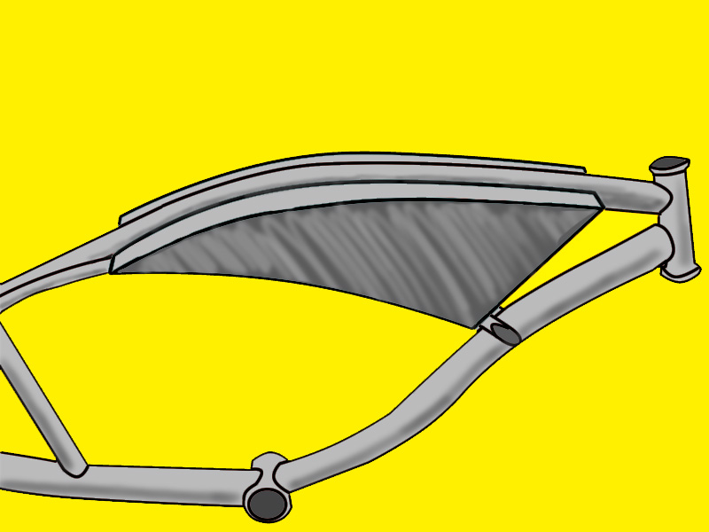
I've been working on an enclosure for my controller, the plan is to cut the pieces out of a 2'X2' sheet of 1/16" steel I have. and whereas I could try and cut them out with my angle grinder I do have access to a water jet cutter. problem is I don't have the know how on how to take the measurements and create a cmx (correl media exchange) file out of them in the right measurements. I downloaded correl designer but have yet to wrap my brain around it properly. The most frustrating part is that I have one of the pieces is curved, well actually two of them as it is the same on both sides. I have a picture I took of that piece but as I said, this corel program is very foreign to me. Is there anyone out there with any experience with this kind of thing who could guide me through the process? or better yet whip up a file for me. there are six pieces, one that is 7 and 1/2" by 5", one 17 and 1/4" by 5", two at 23 and 1/4" by 2 and 5/16" and two pieces like this
side.jpg

the length of the line on top is 23 and 1/4" and the bottom 17 and 1/4" and the front is 7 and 1/2".

any help at all with this would be greatly appreciated. to give you a better Idea of what is going on here is a drawing I did of what it should look like
finaldesign.jpg
 
I don't know cmx, but there are two ways to measure.

one is X,Y where you give a cordinate

The other is polar, you give how far(length) and the angle.
some calculators have a function button where you can transpose one measurement into the other
I assume that's how the program sends commands to the jet.

good luck.
 
If you have the template allot of places will scan it & convert it for you. I've had manifolds made like that from gaskets. Call a couple of places up and ask.
 
gestalt said:
two pieces like this
side.jpg

the length of the line on top is 23 and 1/4" and the bottom 17 and 1/4" and the front is 7 and 1/2".

In practice it would be easiest to have your template scanned at a place set up to do this.

In principle you can make an accurate drawing or CAD file from the photo. This is more often used when the template cannot be removed, and is called photogrammetry (or geomatics if it concerns mapping of large areas.) The process involves undoing the projective distorsion introduced by a projective camera.

Steps are:
1. Draw a precise rectangle on a flat background (as in your picture) using e.g. a builders square or some other means to get it straight.
2. Measure the corners of the rectangle of the paper.
3. Take a picture of the template inside the rectangle using a decent camera (e.g. SLR with a 50mm lens), measure the corners of the rectangle in the picture. (many picture handling softwares will let you click on a position and then give you the pixel coordinates.
4. Derive the parameters for a projective homography http://en.wikipedia.org/wiki/Homography
5. Transform the image using the homography.

Now the transformed image is in the coordinate system of your rectangle. If you had measured the rectangle in millimeters then the transformed image is a precise, to scale drawing in millimeters of the piece in raster format. To make it a vector drawing you could put the transformed image as a background layer in a drawing program, then draw the curves on top in a separate layer so they align with the curves in the image.
 
jag said:
gestalt said:
two pieces like this
side.jpg

the length of the line on top is 23 and 1/4" and the bottom 17 and 1/4" and the front is 7 and 1/2".

In practice it would be easiest to have your template scanned at a place set up to do this.

In principle you can make an accurate drawing or CAD file from the photo. This is more often used when the template cannot be removed, and is called photogrammetry (or geomatics if it concerns mapping of large areas.) The process involves undoing the projective distorsion introduced by a projective camera.

Steps are:
1. Draw a precise rectangle on a flat background (as in your picture) using e.g. a builders square or some other means to get it straight.
2. Measure the corners of the rectangle of the paper.
3. Take a picture of the template inside the rectangle using a decent camera (e.g. SLR with a 50mm lens), measure the corners of the rectangle in the picture. (many picture handling softwares will let you click on a position and then give you the pixel coordinates.
4. Derive the parameters for a projective homography http://en.wikipedia.org/wiki/Homography
5. Transform the image using the homography.

Now the transformed image is in the coordinate system of your rectangle. If you had measured the rectangle in millimeters then the transformed image is a precise, to scale drawing in millimeters of the piece in raster format. To make it a vector drawing you could put the transformed image as a background layer in a drawing program, then draw the curves on top in a separate layer so they align with the curves in the image.

Could also use Img2CAD http://www.img2cad.com/ I used it and it works great.
 
marty said:
Could also use Img2CAD http://www.img2cad.com/ I used it and it works great.

Thanks for the link. The program seems aimed to take raster images into vector formats. It may be aimed to convert scanned drawings, which are geometrically undistorted representatons of a drawing. It is not clear if it can correctly undo the perspective distorsion from a camera photo though it has this line in the description:
Automatically straighten images to a reference line.
It may be aimed to fix some line scanner related problem. Rectifying a perspective image of a planar drawing is impossible from one reference line. At least four reference lines (or points as mentioned before) are needed. Hence the first 5 steps of my post above may be needed. There may be nice softwares that automate this also. Or should someone want to do it I can send matlab/octave code, but it is just a subroutine you have to call from the command line. No GUI.
 
Back
Top