MH1 18650 Capacity - puzzled

pickworthi

100 W
Joined
Oct 1, 2020
Messages
129
Location
UK - Oxfordshire
I have a batch of MH1 cells - manufactured together so near identical if I understand things correctly.

I've done a discharge test on one cell from the batch, and on a 10s4p battery that I built from the batch.

The thing that is puzzling me is that I found the single cell provided 2012 mAh on its discharge test, but the 10s4p battery provided 9826 mAh. I seem to have magicked 444 mAh per cell extra out of the pack - hence puzzlement.

Tests were performed using an iCharger 4010DUO.
The tests were done in the same place at the same temperature (shed - 15 to 16 degrees C).
For the pack, I discharged at 7 amps constant, for the single cell at 1.8 amps constant. The 4010DUO discharge goes CC to 35 volts, an then goes CV until the current drops to 10%. Starting point for both was a full charge, finished 5 minutes before discharge started.

Since this is physics, not magic, I know there is an explanation. I'm hoping someone here can help me find it.
Thanks in advance for any insights.

I have graphs as follows (bottom axis is time in minutes, with hour marker each hour, apologies for cropping off the caption):
Single cell discharge:
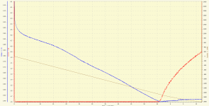
Discharge-cell.png

10s4p Battery discharge:
Discharge-pack.png

Happy to share the raw log data if someone wants to look at that.
 
The 4010DUO discharge goes CC to 35 volts, an then goes CV until the current drops to 10%.
That is a very unusual discharge method ?
Certainly not the normal way most discharge tests are done,and unlikely the way that LG would have tested them .
And “until the current drops to 10%.”..... 10% of what ??.. the set discharge rate ?..
But, i see that the final sinishing current on the single cell is 0.9 A,. Thats 50% of the discharge rate..
..whilst on the 4p pack it is 0.4A ..(0.1A/cell) ?...which is <6% of the discharge rate
The single cell test had more capacity left to drain...it is a 3200mAh cell
Maybe that is the difference ?
I would run the tests again , making sure the final current cut off is the same per cell and also that the actual discharge rate was the same 1.8A and 7.2A
Also why not take them to the manufacturers full discharge minimum voltage (2.5v) ?
And even try some different discharge rates ..1A and 4 A ??.. 2.5A and 10A ? ??
...personally, i woud ignor the data after the initial min discharge voltage set point
.... but i could be mis reading those charts completely ?
https://lygte-info.dk/review/batteries2012/LG%2018650%20MH1%203200mAh%20(Cyan)%20UK.html
 
The C-rate has a **drastic** impact on Ah capacity.

And a larger grouping will always be higher capacity than the sum of the cells in parallel

google "Peukert's Law"
 
I expierenced something similar but with larger pack a 3s16p pack. I tested all the cells with the opus and it equaled 27ah per parallel branch of cells, the pack was a 3s 11.1 volt 27ah pack. But when it was fully charged I checked with a dc wattmeter during discharge (about 6 amps max discharge amps) until the bms cutoff the dc wattmeter showed a capacity of 31ah's, I recharged the pack (at 6 amps) and it took 31ah to fully charge.
I suspected that since the opus tested at 1 amp discharge it gave a lower MAH then if tested a lower discharge amp rate. Since the battery pack isn't discharged at 16ah constantly, it will give me a higher ah reading.
 
Also, note that measuring Ah flow on the **charge cycle** side is irrelevant as a measure of capacity.

CEF Charge Efficiency Factor is a variable that needs to be objectively measured, and wildly varies not just by chemistry but for each cell model, and as a given pack ages.

Only the discharge from 100% down to 0% SoC counts,

and ideally not using coulomb counter gear, but precisely timed true CC discharge

below a 0.1C rate if trying to compare to vendor ratings.

______
If you are charging up to the data sheet maximum voltage (too stressful, do-not-approach in sensible normal daily cycling)

then as you go past the resting-voltage "normal Full without surface charge" point

most of the current flow is no longer being stored as actually usable energy available for subsequent discharge

but just useless and longevity-reducing (aka "damaging" afaic) chemical activity and dissipated as heat.
 
Thanks for the responses.

I'm not trying to determine if the cells are at manufactured spec. I would like to try and find a way of predicting a battery usable capacity from a single cell.
Saying a 4p MH1 pack has a capacity of 12400 mAh (i.e 3100 x 4) is meaningless to me, since I would never discharge below 3.5V on the road.

Hence the cut off level of 3.5V per cell.

7 amp discharge for the pack was based on that being my controllers rated continuous current. 1.8A for the single cell was approximately (.05A more) a quarter of 7, which should give very close to the same C rate for both. Again, not trying to be precise, but I'll look into getting an exact C rate match.

I did a pack discharge at 15amps (max for my controller, and to test its discharge fuse) and got pretty close to the same output capacity. The pack, I am concluding, will give me around a usable 10Ah on the road based on this. Final test will be riding with a watt meter.

Hillhater pointed to an obvious difference I missed, the current cut off point.
Going back to the settings the 4101DUO was configured to stop discharge when the current reaches 50% of the original discharge rate (not 10%, I got the charge cut off confused with discharge, sorry).
Not accurately though, since the 4p pack current stop point was 0.4A, not 0.7A. That gave the pack longer to squeeze out the amps.

So I'll run another single cell discharge with a cut off as close to 0.1A as the 4010DUO will allow. I'll report back when I have some more results.
 
If you are trying to replicate the situation the pack will see in use, then forget the last part of that discharge program on the Icharger....the pack will never see a CV discharge past the 3.5 min set point on the BMS/controller
But why cut off at 3.5v ?..those cells will happily run down to below 3.0v, and even if you only go to 3.0v, that will give you an extra 1000mA per cell.... thats an extra 50% capacity ! :shock:
 
There are many posts on this forum saying that the best low voltage cut off for Lithium cells is 3.5V. Based on reading these posts I concluded that this was a strategy for prolonging the life of a battery.

Is your view that regular discharge to 3.0V per cell will be OK? Or does it depend on the cell one is using, so OK for MH1 but not others?

Also, in my case, no BMS. Well, accurately, I am the BMS. Along with some low voltage alarms plugged in the balance ports.
 
Remember the saying about opinions are like A55holes....?....every body has one !
The most commonly used “guideline” , is the 80/20 % rule...ie avoid using the top and bottom 10% of the cell operating capacity. Obviously no perfect for all cells. , but a sensible start point.
But you are avoiding the lower 50%+ of the cell capacity !
So, you may want to ask yourself why you are testing from a “full” charge ..4.2v ?
With many cells , there is not a lot of capacity below 3.5 v,..but with the H1 there obviously is..even your results show that.
Its also believed that cell life is more determined by high charge and/or discharge rate, high charge terminal voltage, Time at high voltage , low temperature charging , etc etc
But most cells wont suffer from an 80% capacity discharge....especially at conservative discharge rates.
 
Hillhater said:
Remember the saying about opinions are like A55holes....?....every body has one !
My favourite actor - Clint Eastwood :D
This is one of the main problems in gathering information in this forum (and Internet in general) - telling actual experience/data apart from opinions. I've just started with DIY electronics and batteries, so not very good at it. That and the fact that my search skills truly suck. :(

Hillhater said:
So, you may want to ask yourself why you are testing from a “full” charge ..4.2v ?
With many cells , there is not a lot of capacity below 3.5 v,..but with the H1 there obviously is..even your results show that.
Its also believed that cell life is more determined by high charge and/or discharge rate, high charge terminal voltage, Time at high voltage , low temperature charging , etc etc

So, re-evaluating my life choices in this department. I've been studying the graphs at the link you provided:
https://lygte-info.dk/review/batteries2012/LG%2018650%20MH1%203200mAh%20(Cyan)%20UK.html

(Thanks for this - another resource I can use for sifting of above problem.)

Starting with a full charge:

  • Assuming discharge between 1 and 3 amps.
    It looks to me like there is close to no capacity loss in stopping a charge at 4.1V. There appears to be a small loss of capacity at 4.0V.
    Does a compromise charge endpoint at 4.05V avoid "high charge terminal voltage"? Or should I go for something a bit lower, such as 3.98V around where the 3A curve bends to a straight line?

As for low voltage cut off:

  • Again, assuming discharge between 1 and 3 amps.
    The "knee" on the graph seems to develop at around 3.3V. At 1A discharge the curve quickly goes vertical after that.
    It would thus appear to be getting riskier below 3.3V, or am I reading too much into this?
  • My controller has an absolute low voltage cut off at 30V (so 3V per cell). I've tested this with a variable power source, and see it as reliable. By that time the readout on the controller display is flashing very vigorously - so I am really unlikely to go that far. At 3.2V ish it shows me one bar, flashing. I can adjust my low voltage alarms to 3.2V per cell to help remind me.
  • So.... after all that thinking aloud does a 3.2V end voltage for my "realistic" test seems good?

As I said at the top of the thread, I appreciate any insights that are offered, and particularly appreciate your responses on this. Many thanks
 
pickworthi said:
I'm not trying to determine if the cells are at manufactured spec. I would like to try and find a way of predicting a battery usable capacity from a single cell.

So measure the capacity of a single cell using **your** working definition of 100% and 0%, at a CC rate that you believe is "average" for your use case.

To be conservative, increase that last to get a lower Ah capacity.

Then multiply that number by the average DoD% you intend to draw down to in normal use.

And multiply again by how may cells in parallel.

So, for my 180Ah LFP cells,

my 100% is CC-only stop at 3.45V at 60A (0.33C), no CV/Absorb time.

My 0% is 3.0V at a 0.2C rate, which would yield capacity of 165Ah per cell.

I like to stop discharging at 75% DoD for good longevity, so

"usable" capacity is ~124Ah.

I have a 3P layout, so for the bank as a whole is 371Ah

A few years from now, of course all those numbers will be a bit lower as the bank wears.

______
> Final test will be riding with a watt meter.

That is great for repeatability in Real Life use, but not nearly as objectively accurate as a precisely timed CC load test.

______
There is no current based cutoff - based on trailing amps - for discharge

that is only relevant to stop-charging

determining the CV Absorb stage hold time.
 
pickworthi said:
There are many posts on this forum saying that the best low voltage cut off for Lithium cells is 3.5V. Based on reading these posts I concluded that this was a strategy for prolonging the life of a battery.
The lower the DoD% the longer the lifespan, that is true.

But voltage under load does not give DoD%

you need to isolate the cell say an hour to get resting voltage.

The higher the current at cutoff the more voltage bounces back during recovery.

Stopping "too soon" (at a higher voltage cutoff) means less capacity utilization, so you have to buy more battery, carry a bigger pack to get the same range.

It is a "balancing act" decision, up to you.

90% DoD would mean maybe half the lifespan of stopping at 80%.

And a 70% cutoff can give double again, depends on the chemistry.
 
pickworthi said:
Assuming discharge between 1 and 3 amps.
It looks to me like there is close to no capacity loss in stopping a charge at 4.1V. There appears to be a small loss of capacity at 4.0V.
Does a compromise charge endpoint at 4.05V avoid "high charge terminal voltage"? Or should I go for something a bit lower, such as 3.98V around where the 3A curve bends to a straight line?....
Generally the “harm” to the cell is believed to become noticeable with extended periods above 4.1 - 4,15 v, with as you say little or no capacity to be gained ...on most cells.

pickworthi said:
As for low voltage cut off:

  • Again, assuming discharge between 1 and 3 amps.
    The "knee" on the graph seems to develop at around 3.3V. At 1A discharge the curve quickly goes vertical after that.
    It would thus appear to be getting riskier below 3.3V, or am I reading too much into this?

  • You are assuming <3.3 v is a indicator of remaining capacity...but it will depend on discharge current.
    At 3.0 A ,.. 3.3v still leaves 0.4 to 0.5Ah in the cell before it gets to the “knee” ....and you are only using 75% of the total capacity.
    3.2v will release an extra 10% capacity.
    And the main reason for not running deep into the “knee” part of the curve, is that there is little capacity available there.
    On your cells , at 3A discharge , 3.2 v will prevent you getting down in that zone
    pickworthi said:
    So.... after all that thinking aloud does a 3.2V end voltage for my "realistic" test seems good?
    Yes, ..and should give you much more available pack capacity ( 11.2 Ah) compared to the 3.5v cut off setting ( <7.5Ah ) :bigthumb:
    Obviously, you should test at those settings to confirm these predicted results.
    FYI....
    Cell life is a vague area with little firm info for specific cell, but for someone even recharging charging daily ..(but who ever does a “full” recharge daily ?) ,...you can expect many years of practical use with little degridation.
    And by the time you need to replace the pack,..these cells will both be superceeded by something much better, and also so cheap you will be able to pick them up at the local Supermarket like bags of Carrots..and just as cheap ! :shock:
    ( well, anyway,... that is what those battery “experts” keep predicting about the cost of lithium cells ! :wink: :p )
 
I've re-run my tests, this time with the following adjustments:
  • Full charge set to 4.1V per cell
  • Discharge cut off voltage set to 3.2V per cell
  • Single cell discharge at 1.8A, 4p discharge at 7.2A, so both .58C
  • Disabled balance at end of discharge for the 4p pack (forgot that one before).
Results:
  • Single cell discharged 2495 mAh
  • 4p pack discharged 10204 mAh

(Taking data from the MH1 datasheet, although they say its a "nominal" 3200 mAh cell, all the C values are based off 3100 mAh. So I'm taking it that 3100 mAh is 1C for this cell.)

From my original tests, I got 2012 mAh for a single cell, and 9826 mAh for the pack, so a discrepancy of 444 mAh - 4.5% of pack total.

This test gives single cell to pack difference of 224 mAh - 2.2% of pack total. So the changes to make the C factors for both the same yielded some improvement.

Also, the discharge to 3.2V per cell rather than 3.5V per cell yielded and extra 483 mAh per cell. Which proves @Hillhaters point I think.

Having studied the data a bit, it appears that my connectors for the single cell test are not that good.
The 4P pack shows internal resistance of around 10 milli ohms per bank - so 40ish milli ohms per cell (if Kirchoff's law works for parallel batteries). That is inside the datasheets assertion of <= 40 milli ohms per cell (although I don't know what it's assertion of "without PTC" means).
For the single cell, the internal resistance is showing as around 100 milli ohms. I think that is down to a poor connection in my single cell connectors. I'll be looking into that to see if I can further reduce the cell to pack difference. Will take a while though.

For the pack, 10204 mAh is 82% of the advertised capacity of 12400 mAh (4x3100). Given in these tests I am extracting power in the normal usage range, that seems about right to me.
 
Yes, that extra resistance when testing the single cell will certainly reduce the measured capacity result.
You should be getting 2600-2700mAh at those test parameters.
Are you aware of. The “4 wire” test proceeddure ?.....if not look it up
https://lygte-info.dk/info/Batteries2012Info%20UK.html
 
Since you are trying to get a real-life capacity rather than striving to reach the theoretical nameplate rating

"shoulda coulda woulda" are irrelevant.

Do not bother "improving" your test conditions past what you will be doing "in production"

you are just seeking to measure "what is" IRL conditions.

And personally I think you've achieved that.

Just keep in mind, a higher C-rate will reduce capacity, and v/v

and capacity will drop as the pack ages

in theory EoL at SoH 80% but even 70% should still be OK at least from a safety POV.

 
I think you have hit my particular nail on the head, thanks.

In my view, there is no test, however "accurate", that accurately simulates a real life ride. There are no circumstances where I will subject a battery to a continuous current discharge on the bike. The most common is a medium to high load (i.e. a hill) followed by a rest (i.e. flat or downhill). Since I only have pedal assist, there are many events where the battery will be able to bounce back after a load.
My limited intent with this was to try and estimate a packs usable capacity based on the cells I'm using to construct it. This thread has given me a few more approaches to achieving that.

As I say, my view.
I spent 40 years in IT systems before I retired. The main thing I learnt was that the existence of accurate data fools people (well management - I suppose they are people :D ) into believing that there is accuracy in prediction. Trends and changes are way more important, in IT anyway.

Anyway, many thanks to all for the responses, I have learnt a lot in these exchanges - which is what one hopes for when requesting assistance :)
 
Good, if you are happy that you have resolved the “puzzle” that initiated the thread.
FWIW.. im pretty sure that with a carefully controlled “4 wire” type test, the single cell would yeald the same as each cell in the “group test”. ( Within EE )
 
Back
Top