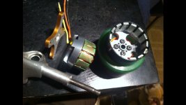
My in-da-hub motor mount attempt

Joined
Apr 25, 2014
Messages
3,049
Location
Sausalito
image.jpgContinuing. Whether the rotor crashes into the stator with weight or if the bearings die I will find out. The bearings include (8) 5/16 by 1/2 inch and a thrust bearing. At this point I sit trying to true the rotor to the axle. I've gotten it to 1/100 an inch but I think the internal space of a motor is 3 and there's more I can do to get there so I'm not trying it yet. The skate axle isn't perfectly straight either so I'm fixing the stator with epoxy instead of the mounting plate seen here and I'll add a keyway. Since the axle isn't straight I'm going to set the stator's position by using two layers of duct tape between the stator and rotor to hold it in position to where the rotor will spin while it sets.

I've found u can reterminate a motor to wye outside the motor, which I've found a lot easier than opening it up and somehow removing the bearing tube. I'll do it later if all else is good. This'll give it more needed torque which is needed since there's no gearing.
But...the one in this pic sits with the bearings stuck on with "retaining fluid". Pretty much glue. My better recent attempt I'm using a tacon 160. Probably harder with its length

The rotor holds it's position on the axle by being bolted to a 2 inch bearing-filled tube that sits in the wheel.
 

Attachments

  • image.jpg
    image.jpg
    76.7 KB · Views: 1,039
How are you supporting the end of the rotor? Shouldn'tyou be using a motor with a skirt bearing? Wouldn't it have been easier to use the SK 8 king trucks?
 
It's just supported on one end. But so is a typical outrunner anyway. I'll look up those. Next time definately diff trucks. But u can't know if there straight till u spin them on a lathe. Unless u tell me they're straight
 
I assure you it will not last without the skirt bearing. The little bearing holding the rotor on one end is not enough. There is far too much vibration from the wheel that the magnets will eventually touch the stator. Some SK3 MOTOR have skirt bearings in them.
 
A wayward rock hitting the can or the accidental scraping will make those magnets kiss the stator. You have to protect it like Justin did.

Hummina Shadeeba said:
...Next time definately diff trucks. But u can't know if there straight till u spin them on a lathe. Unless u tell me they're straight

With the Sk8kings trucks, all you have to remove is the shaft from the motor. Then you can just slip the motor onto the axle. You probably will need to drill a keyway on the axle to prevent the stator from spinning.
 
The sk8kings are very expensive. Surely there's a straight axle out there for cheap. I could even take a ten cm and lathe it to an 8cm.
I can't find skirt bearings in a yahoo search or a store. I imagine u mean something wide on the outside.

We will see. I think Justin's was supported on one side with a skirt bearing or two. This was less parts maybe so it was attractive to me.
I can't think of a good reason or won't work though. Tell me why
 
Hobbykings sk3 motors that have screws on the can usually indicates a skirt bearing.
Hummina Shadeeba said:
We will see. I think Justin's was supported on one side with a skirt bearing or two. This was less parts maybe so it was attractive to me.
I can't think of a good reason or won't work though. Tell me why

If you re-read Justins thread, he actually mentioned that the motors got a lot of nicks and dings, being that the motors are so close to the road. He actually proposes to put the motor can more inside the wheel to protect it. You can just use a plate to protect the motors, just like onloop's trucks. But I would still highly suggest a skirt bearing.

If you get this right, you can sell this as a kit and it will be the most awesome one. :)
 
I'm trying to make one work
Here now trying Truing. Spinning n measuring. I need a jig or something to reset the rotor to the tight center spot. Do e this for hours. It's so hard to adjust. Had it n fiddled with it and lost it

Doubt anyone wants to do this part
Not as easy as a bike wheel
 
If you have a bearing in the outrunner case and bearings in the wheel I don't understand how there will be any ill effects to the motor. 3 bearings right?
 
9 bearings. (8) 5/16ths(skate axle is not 8mm) by 1/2 inch ball bearings in the tube and a thrust bearing between the stator n rotor. The tube is 1 and 1/3 inches long and u can see how thick it is. It's 6000 something aluminum. Cut not cast. It's likely stronger n better suited than something cast for a reasonable cost for one or two. The bearings could be bigger though I imagine and a thinner tube maybe.
It's a tight fit on the axle and it doesn't move. Seems as secure as the other one I haven't taken apart

But I'm not thrilled with it because after spending another night trying to adjust the rotor with a needle and dial good to 1/1000 inch and four screws I want to Locktite in place I'm always about .007 off and I don't want to lock it down. I'm going to have to make some clamping gig.


But will it work anyway. I'm this far so I'm going through with it. In hindsight and probably forward I'd like a squirrel cage motor in the truck hanger. If any of you know why that won't work please tell me now.

I'm making a traditional 2 pulley mount on the cad cnc machine Reallly choking soon! This obsession has gone on long enough. If u want a mount cut out on there the same as mine I'll do u one. Takes maybe an hour with setup and the aluminum is really cheap. Last time I had time on the machine, and wasn't making another tube, I set the speeds wrong and dug a loud hole n snapped the endmill. Next time.
 
How did you manage to change the Kv ratio to a usable speed? Generally motors with kv's of around 150-250 with no torque multiplier from the drive train would give you around speeds of 50-100 mph.
 
moosejaw said:
How did you manage to change the Kv ratio to a usable speed? Generally motors with kv's of around 150-250 with no torque multiplier from the drive train would give you around speeds of 50-100 mph.

Not sure where that figure came from, because I get 30mph @ 150kv (22.2v, 80mm wheels)
 
My last attempt with this plan. Going to make an inrunner version with supporting bearings on both ends next time and a floating axle. Most would call it a failure but I learned what not to do. Thought this would be an easy way to do an inline motor and It's pretty much the abec in-the-wheel-pulley around a tube filled with bearings bolted to the rotor, and a thrust bearing butted against it. I'm not saying it couldn't work but I'm moving on

I have a mounting plate and only need a belt and that's happening in a week. Been here for months without a board still.
 

Attachments

  • image.jpg
    image.jpg
    29.9 KB · Views: 3,140
Hummina, just keep going. I've been here for almost 2 years, been a long time lurker even before that, and I've learned a lot. I'm proud to say I'm about to launch my Kickstarter campaign. I could have started a campaign way before, but it would have been half-baked. I'm not saying my campaign will be successful, but at least it's different.

You may think all this time and effort are for naught, but you will find your "aha" moment, your own eureka. Believe me, I've done a lot of pivoting (i mean marketing wise, not just riding, lol) and I've found out that it's better to take your time.

There's a lot of clutter in the E-skateboards right now. The trick is to find your niche-of-niche-of-niche-of-niche market. Then you can stand-out.

You also have to ride your board man. All these speed, distance, etc. calculations are good on paper, but IMO, it's the UX that will matter.
 
Not the best picture but I broke my phone camera while roller skating which I do a lot more of than skateboarding. But I do neither now as it's been a 9month groin injury and I'm starting to believe I have to stop moving. I figured an electric skateboard would be perfect for that.
I finally get paid after a summer of not working and spending everything on this rediculousness. I think even if I finished it and it didn't self-destruct with a pothole it's not a good design and I'm working on another one and I'm still excited about making my own mount. This is still fun to me but when I get paid the simple plate mount will get welded and I'll be beyond just trying to make a strange mount and up n moving! This has been fun but that's definitely going to be fun
What's XU?
 
fully agree with pediglide...
Do your motor.. make it work.. once it goes 2000 kms without breaking down... go for it...
Ride..learn...fix..reinvent..repeat..
good luck
 
I agree as well. You're probably closer to pulling it off than you think!
What if you mounted your stator to the truck hanger like you did, but then used a long axle, attached to the motor housing? The axle would spin freely in the hanger (like Lagrange) but would drive the opposing wheel on the non motorized side. The bearings on that side would just be solid plugs in the wheel so it would be fixed to the axle.
The wheel on the motorized side would spin freely on normal bearings.
This way, The axle would be supported on bearings all the way through the hanger, placing no stress between the motor/stator.
 
Thanks for the encouragement but don't worry im psyched on my next design. Not that I've done anything. All I plan to
do in the futures is a inrunner of some sort and I found that even a coreless inrunner, with no electrical steel and just wire winding and magnets, could maybe get the power needed. Definitely two. But a steel stator will give greater magnetism and torque that's needed with the 1:1 especially to be efficient. Getting one that's 5.2x23mm would have to
be custom made and very expensive. At this point I'm looking to see if a steel filing or powder and epoxy stator core
would be beneficial. Regardless I'd be setting the windings with a plastic inner tube
wrapped in saranwrap or something till it sets I epoxy. Maybe a thin steel tube to help. And then the rotor being a long 10mm or 8mm shaft with long magnets set in a halbach array ( weird placement that makes them stronger, don't know why it's not ever sold) epoxied in and possibly further held with thin carbon r Kevlar. And fat bearings on both ends and a strong outer casing it ll be in. That's my latest plan
Tiller it's hard to imagine when a pic would say it all but while the outrunner is a stronger motor getting the rotor to connect with a spinning axle is much harder to me than just making a spinning axle to begin with. I'll re read what you wrote but that was my question at first read. . Inrunner much more
mechanically simple I think.
Check this coreless stator set in epoxy.
http://www.thingap.com/ironless-composite-stator/

http://www.flyelectric.ukgateway.net/balancing.htm
 
I think its a cool project. I'd fix the end of the motor positioned like in your picture to a small mount welded to the the hanger. Then bolt the other end of the motor to the wheel. Opposite of what we normally do. You would then have a super compact setup. Biggest issue is you won't have gearing reduction, so need a 90kv or so motor. I don't recall how Justin did his build. Wish that thread would get updated, because that is really the holy grail of this whole thing. A hub motor you could slide on and off your board would be so sweet. Trucks already use an 8mm axle. Should be easy. Kickstarter that.
 
Nice one tiller. I'm smitten and staring into space thinking about it. I Think i almost bought a la grange board from
You months ago. I always wanted to see how it's axle was fixed from sliding laterally. What butts against what or it
All held
By the end nuts? I would try your way and with two 50mm cans on one axle. But I don't want to try to do the work of the many operations to finally complete it. It's taking a motor apart and then trying to put it back together again. Complexity that makes me definitely want to make an inrunner.

With Repurposing the outrunner one limitation is the stator's .7 inch inner diameter which limits the tube outer diameter, so small bearings.
I want to use standard or larger bearings on a simple 10mm shaft with just magnets simply glued and threaded at the ends. All I'd need other than that are a tube with bearing seats cut in the ends. And then inside a thin ramen noodle copper waffle in epoxy and.. stator dust?.. Doing the arranging on the tube outside surface then inserting it and gluing to the motor casing inner surface. Tolerances could be well controlled. Gluing on the magnets a jig could be made to be precise using a laser or something. Lots of glue,magnets,thin shiny copper wire, the tube and lasers are all I need maybe
I'm into it.
And I'm still doing things to make this outrunner go. Like cut the backs of the screws for tightening from the outside, du and I'll be back at truing it soon again. I'll always be able to find where it's rubbing and center it somehow.
 
Diggler I don't understand what you would do differnt with the design. As for the mounting plate I made one earlier but jammed it all up, got differnt trucks.and motor, and went with a keyway cut in both sides and steel-epoxy rammed in. There's a pic of my jammed on somewhere here Welding is a pain.
 

Attachments

  • image.jpg
    image.jpg
    67 KB · Views: 1,025
  • image.jpg
    image.jpg
    59.2 KB · Views: 1,025
Yeah, the inner diameter of the stator would be a factor...Would it be difficult to have the stator sheets cut with a different shape/size in the middle? you could kill two birds with one stone that way. If they were shaped like your hanger profile they could anchor into position. Then, the outrunner, with it's longboard length axle would slip through the hanger and all of its bearings.
 
Getting a stator made to specs is expensive. I think I was quoted 300$ I'm
hoping to find a diy alternative like coreless or see if a ground one can be reformed w epoxy, or grind the teeth off
outrunner ones (which are common in office supply trash) and just use the inner cylinders of them glued together to wrap windings on as an Inrunner. I don't know what's possible and can't find the right links and the motor
Gurus here and rc groups aren't answering. But I wanted to work an outrunner into it and it seemed easier but I feel safer going this way. Simply getting the motor can permenantly bolted in the right spot has been rediculous. But at least with your design you'd have a better straight axle and stator seat starting point to wrk with. A fat bearing at both ends though makes things much easier and safer all round. Come to the inrunner side.

At the bottom of this. That motor encourages me to believe an inrunner could be made that would fit and be a suitable kv and do the watts
http://www.castlecreations.com/products/neumotors/nm1900.html
 
There are a few blogs from MIT rocket science students that have made working versions. Here are a few links:
http://thevariableconstant.blogspot.com/search/label/HardBord Using 6364 motors and custom trucks
http://www.mitrocketscience.blogspot.com/search/label/ELB
http://s907.photobucket.com/user/all1by/media/ELB/ELBfirsttestrun.mp4.html?sort=3&o=0 Video - Granted it was a few years back, but anyone that rides a board in Tevas...
Hope something there might help you. I'm always surprised at how close some of these builds were to being commercial breakthroughs. A ton of good ideas and thought went into these builds.

Maybe I misunderstood where you were stuck, without seeing exactly what you did to the truck, but I was wondering if you could fix the end of the motor to the truck. Then have the spinning portion of the outrunner turn the wheel, to which it is attached.
 
Back
Top