Simplifying my balance charging process

billyjones454

100 mW
Joined
Feb 16, 2011
Messages
44
I use 8 5000mah 5S lipo batteries in a 20s2p configuration for 74v 10ah.

At the moment I break the pack back down to 5s each time I charge, which is kind of a tedious. I'd like to simplify the process, and I think that my new setup will work, I just don't want to fry anything, so I thought I'd get some feedback before I move forward with the process.

This is my idea:
FkrO02q.jpg


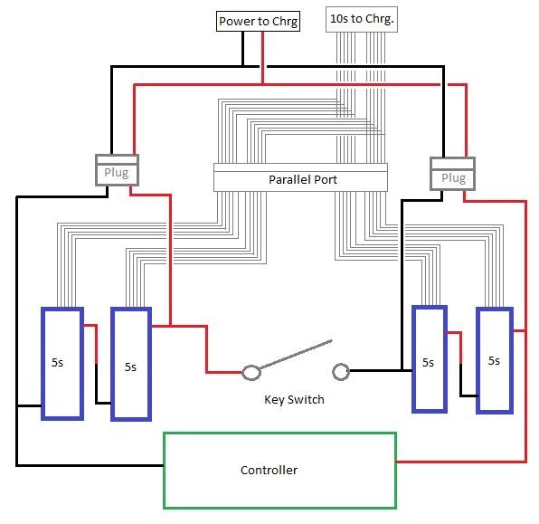
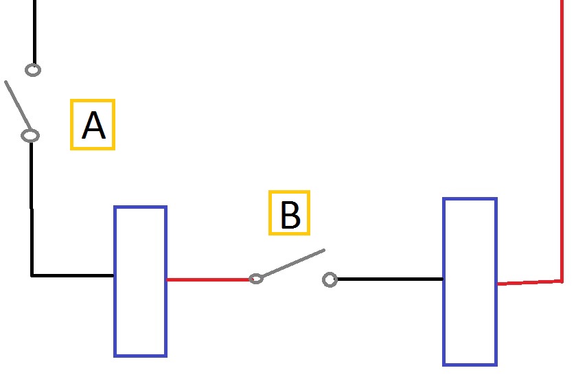
Basically the key switch that I use (Crystalyte motor/controller/switch/throttle kit) will separate the pack's main leads from 20s to 2 x 10s packs. AFTER the main leads are disconnected, I plug in my parallel port which will put the 2 packs balance plugs parallel. When I plug my main leads into the charge harness they will be paralleled also. This allows me to charge the whole pack as 1 10s 10ah pack.

This biggest concern I have is how well the packs will stay in balance. If they are out of balance significantly and I plug in my serial port, wires are going to melt, at best. What do you think the likelyhood of that happening would be (hard question to answer, I know)? Also, will there be any ill effects of having the controller leads still hooked up? I could add an additional switch to disconnect the controller too...

Thanks for any and all input.
 
NO !.... You do realise if you close that switch before unplugging the charge circuit, you will short all your packs !!
Recheck your circuit , and at least make it a multi pole switch to prevent both circuits being live at the same time.
Also, you will have 10s of charging power to the controller when charging.?
There should be a software simulation prog for this so circuits can be checked for basic functionality before being constructed.
Better to get a 72v bulk charger and a few Cellogs.
 
Yeah, if it can happen, it will someday.

Here's a suggestion for you. Run your battery in such a way that you don't need to balance so often. I've been doing lipo packs for years now, doing a conservative enough protocol to make bulk charging less risky. Some years, I balance 4 times.

This is not packs used daily, but for sure at least 2-3 times a week. Bottom line is, balancing the packs is oh so easy when you stop forcing them out of balance.

I charge to 4.15v, and generally stop no later than 3.6v or so, for RC lico packs. If the cells are within .1 to .05 of in balance, then no problem with a bulk charge to 4.15v average. Worst case is a cell gets charged to 4.25v.

I do, of course, check cell balance frequently. But no need to actually balance to .1v every cycle. No need for that at all.
 
izeman said:
because dnmun is offline right now, i'll take his part: USE A BMS :)
this will make plug on and off obsolete for once and always.

I strongly agree with using BMS for hi/lo Voltage protection for charge/discharge but IME bleed balance function of majority BMS just doesn't work that well in practice.

Common 60-80mA is not much bleed current for 5, 10, 15, 20Ah cell channel groups and then you must use a non-latching charger to even operate balance/equilibrium function.

But as the good DogMan has mentioned here, avoiding deep discharges will avoid most, if not all need to balance healthy RC Lipo cells.

I love the protection of BMS, just never been impressed by the balance function. Especially, since it's not often needed for this chemistry.
 
izeman said:
i agree. i recommended the d131 because it has the highest balance/bleed current i know of. it's still a mere 140mA. but better than nothing.
and as i tend to no go below 3.6V my battery is never really out of balance. if it was i would realize as charging would take forever. ;)

You can "tack on" lower resistance resistors but you must be ready, wiling and able to deal with the added heat higher balance current creates. It's just "one of those things" which sounds like a great idea until you actually live with it over a period of time.
 
BMS a darn good approach too, especially if you have sorted out and removed any weak packs, and treat them nice.

Having a bms that prevents over discharge is one easy way to treat them nicer.

I was just trying to point out that being .01 or even .05v out of balance is not a big deal. Balancing in a way that is quite a hassle is lots easier if you only need to do it 4-6 times a year.
 
billyjones454 said:
I AFTER the main leads are disconnected, I plug in my parallel port which will put the 2 packs balance plugs parallel. When I plug my main leads into the charge harness they will be paralleled also. This allows me to charge the whole pack as 1 10s 10ah pack.

This biggest concern I have is how well the packs will stay in balance. If they are out of balance significantly and I plug in my serial port, wires are going to melt, at best. What do you think the likelyhood of that happening would be (hard question to answer, I know)? Also, will there be any ill effects of having the controller leads still hooked up? I could add an additional switch to disconnect the controller too...

Thanks for any and all input.
I used to have a setup like that I used it for a fair while but it was always a weird feeling that I was merely a switch away from mass destruction.
One idea I thought about was to replace the switch with merely a large nib magnet that would sit between the two main halfs of the battery, the half terminals would be steel nut/bolt setup I was thinking..
Once you removed the nib the parallel charge ports would be exposed underneath it so that way its impossible to accidentally charge without splitting the battery in half.
The nib getting in the way of the parallel charge ports would be about this size below I had envisioned.
http://www.ebay.com/itm/Big-Super-Strong-Large-Neodymium-N35-Magnet-Block-Wind-Turbine-50mm-x25mm-x10mmW-/221771463561?hash=item33a29bfb89:g:V2sAAOSwNSxVUssZ
s-l500.jpg
 
izeman said:
magnets and steel bolts will add some serious resistance. steel is a bad conductor.
Maybe but the switch I used was pretty basic and it worked fine. I don't think the current flowing through the middle of the battery is big.

Also there are plenty of Zinc or nickel-plated screws nuts and bolts out there. So its the exact same metal composition as 18650 cells.
http://www.ebay.com/itm/8-pcs-M3-x-6mm-Toolless-Thumb-Screws-Nickel-plated-/191302165392?hash=item2c8a7f6390
 
A switch carrying the series connection would carry all the current you are pulling on the EV.
 
TheBeastie said:
I used to have a setup like that I used it for a fair while but it was always a weird feeling that I was merely a switch away from mass destruction.
One idea I thought about was to replace the switch with merely a large nib magnet that would sit between the two main halfs of the battery, the half terminals would be steel nut/bolt setup I was thinking..
Once you removed the nib the parallel charge ports would be exposed underneath it so that way its impossible to accidentally charge without splitting the battery in half.
The nib getting in the way of the parallel charge ports would be about this size below I had envisioned.
http://www.ebay.com/itm/Big-Super-Strong-Large-Neodymium-N35-Magnet-Block-Wind-Turbine-50mm-x25mm-x10mmW-/221771463561?hash=item33a29bfb89:g:V2sAAOSwNSxVUssZ
s-l500.jpg

Right, so there are a few ways that I have considered to make this process more failsafe. I thought about making a plastic plate that had 4 bullet plugs on each corner sticking out perpendicular to the plane of the plate that would act like a 2 pole switch. When you take off the plate one of the main leads to the controller is broken, and one of the main leads to the battery (converting it to 10s). Additionally the parallel port would be behind the plate, so you could not physically plug anything in before the pack and controller were disconnected.

fgpMpab.jpg


My big question was whether from an electrical standpoint (as opposed to a safety and limiting of risk standpoint) there were any issues with my setup.

I want to give everyone a big thank you for their input. The discussion went more toward the safety aspects, vs how electrically sound the wiring setup is. But I think for anyone that demonstrates that they don't have a thorough understnading of batteries,especially while using lipo batteries, it's important to make the risks known. Even if it does not specifically answer their questions.

I like the idea of a BMS, and I've played with the idea of bulk charging (can an icharger 1010b+ bulk charge a 20s pack?). But I'd like to use what I have now. And if I can make my system work safely and predictably for now with what I have, I'd like to make that work.
 
dogman dan said:
A switch carrying the series connection would carry all the current you are pulling on the EV.

So if the switch is between the two packs, vs at a main connector on either side of the pack does it experience a different amount of current?

OdcBdbR.jpg

Does a switch at A, experience less current than B?

Thanks.
 
Found up an old post. (As near to being idiot proof as I could conceive)
Sets up a quick "switch" with the same principle.
6s to 12s as similar to 10s to 20s

DrkAngel said:
Trying to clarify 6s2p
Simplify all diagrams by combining pairs of batteries as they will be used. - 6s2p
Pos & Neg power Y and balance Y to 1st create 6s2p bricks.

44.4V controller (central jumper (loop) is ideal location for fuse!)
Volt meter-alarms attached to balance connectors
file.php

22.2V charger
file.php


KISS ©®

Except for the balance connectors ...
After you pair up into 6s2p, KISS ©®
Charging and running this 22.2V - 44.4V LiPo is exactly the same complexity as 2 - 12V SLA batteries = 24V and a 12V charger.
 
Need an actual "switch"? - $22.47 delivered
DrkAngel said:
Simpler solution! ... ?
12s2p >>> 6s4p switch with full redirect for 12s controller and 6s charger

690V 50A 12 Terminals 3 Positions Rotary Cam Changeover Switch $25.24 - delivered

DrkAngel said:
"Connect:
1- to charger and 1- to controller
1+ to .. 2+ ch .. ll ... 1+ to 2-
2- to ... 1- ..... ll ... 2- to 1+
2+ to ... 1+ .... ll ... 2+ controller"

OMG! This isn't rocket science!

file.php

Confirm switch functions with continuity function of multimeter.

3 wires into the switch, a couple jumpers and 3 wires out.
Don't forget the fuse!!! 40A? (dependent on controller rated amps)

Add/Remove balance Y (not shown) with switch in center(off) position only!!! (charger position might be OK)
Stay sober enough to not "switch" to "controller" while balance leads attached ... nasty, red hot wires melting through other wires and Lipo casings fire>> flames >> etc.
Rig is about as simple and safe as possible ... but nothing is truly "Idiot Proof".

As in my computer work, I strive towards attaining the title of IP Tech ... Idiot Proof Technology-Technician.
Unfortunately, "idiots" are continually coming up with new and improved ways to screw up their computers!
 
I still like that Anderson plug solution a lot. Identical to Icecube 57's series/parallel harness idea.

The key thing about this harness idea, is since you pull a plug and replace a harness to charge, it's virtually impossible to do the old oops, some how got them series connected while still paralleled trick. (still possible with the balance plugs, one of the reasons I never parallel them.)

And it's cheap, just a few andersons and bits of 12g wire.

Screw the switch, and do the Icecube 57 method.
 
Improved picture ... Removed another Y and added terminal number labels
file.php

Idiot proof ... except for balance Y
 
Back
Top