Solder Resistance with .25 copper sheeting clamped flat

Joined
Sep 28, 2023
Messages
56
Location
Long Beach, CA
I was wondering if these bus bar extensions are more resistant prone then I had originally thought.

BUS BAR CONNECTIONS

DID LARGE SURFACE-AREA SOLDERING FOOL MY THOUGHT OF PROPER FLOW?

629E4747-129C-4FAC-92D4-60561BA1595D.jpeg

When two sheets of .25 are joined with the amount of solder (+flux) shown and with that degree of surface area,

• is there a large amount of resistance to be concerned with (I.e. heat/joint/connection failure or unplanned additional power-robbing resistance)

or

• does the surface area connection in comparison to the cross-section of the current path within the two sheets, in total, fall so far below the flat face-to-face offensive soldered joint that the solder joint becomes a non-issue? (My original thought)

———-

Additional concern with similar structure and connectivity

BUS BAR EXTENSIONS

HOW DOES THE THOUGHT OF 2 .15 COPPER STRIPS OF SHEETING ACTING AS PARALLEL BUS EXTENSIONS OCCASIONALLY JOINED WITH SOLDER SIT IN ONES MIND WHEN THINKING ABOUT FLOW/RESISTANCE?

image.jpg

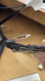
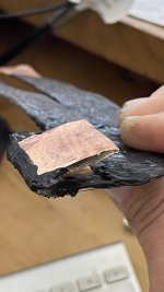
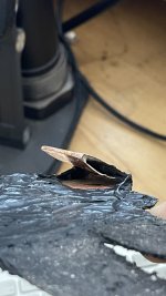
Since most of the copper used is .25 yet at the end of the build I then ran out and am left with .15 sheets, I am then forced to clamp and torch solder (see example of solder/surface area before joined above - and solder always drips out as if too much was applied as clamps close shut) two sheet of now what I considering ‘bus bar extensions’ as if they are just as good as a .25 -and- knowingly seeing that the solder + clamp smashing didn’t result in some vise-like lamination but as more or a two-layers in parallel with intermittent solder bonding. (And see a failed attempt to show gaps, which are there, here and there, below)

Am I creating a problem with ignorance in flow and resistance or lucky at a guess?


• creating a problem - These sheets are about 6-10” of intermittent .15 parallel sheets. Is this just a jumbled city street for the current to flow increasing resistance?

Or

• lucky guess - does the current see that, ‘hey, we’ve got above .25 in two lanes so all is good even though a couple 90 degree turns are made along the way” (my original thought)

image.jpg
 
I forgot to add the configuration and hope:

72V
Molicel P42a
- 330 cells
Sandwiched welded with .25 copper (TY spinning magnets)
Amps and BMS - Would love to go beyond my Ant BMS constant limit of 380 Amps / 950 Amp 10 second max. and be forced into dis bypass but can’t do the damn math to know. :/
Controller - Fardriver 721800 - 800 in/1800 out 8)
Wire - Single 2AWG wires for all
Motor - QS 273 unfortunately with stock thin phase wires 6” out from motor hooked to the 2AWG wires from controller. (Eventually the motor will be split with new axle already drilled (nightmare and with hope of being failure-free) from other side to hopefully allow near 2- 4AWG wires - two from one side and one plus other wires from the other side going directly to stator.)
Bike - CS20 ridiculously modded.
Hope - killer jolting low end and a hundy at the top. ;)


Thank you
 
I think quibbling about tiny connection resistances, when you probably added a bunch more resistance than that inside the cells by dumping in so much heat, amounts to running in place. If you really want low ESR, you should consider treating the cells better.

Nickel strip isn't the customary material because it has excellent electrical properties. It's used because it's conductive enough to do the job, while being resistive enough to concentrate the heat of welding right in the weld zone and minimize the total heat diffused into the cells.

If you want to use copper for lower bus resistance, have a look at the "copper nickel sandwich" thread. Using that layered welding technique will still dump more heat into your cells, just because of the increased thermal mass, thermal conductivity, and specific heat of copper. But it will be worlds better than soldering.
 
Last edited:
But I spot welded the cells. Copper-lacking resistance in sandwiching added too much heat?

Happy to hear connection resistance is low aiming. :)
 
Why not measure instead of guess? Volt meters can measure resistance. Better yet, load test the pack and point a thermal camera at it to check for hot spots.
 
Why not measure instead of guess? Volt meters can measure resistance. Better yet, load test the pack and point a thermal camera at it to check for hot spots.
Double love to that. But there’s always more info if I ask...you know, parallel issues, additional good or bad things on the topic.

I can’t easily do tests without committing my limited copper. But once it’s hooked up, the Flir comes out.

Will do on both. Thanks.
 
I think quibbling about tiny connection resistances, when you probably added a bunch more resistance than that inside the cells by dumping in so much heat, amounts to running in place. If you really want low ESR, you should consider treating the cells better.

Nickel strip isn't the customary material because it has excellent electrical properties. It's used because it's conductive enough to do the job, while being resistive enough to concentrate the heat of welding right in the weld zone and minimize the total heat diffused into the cells.

If you want to use copper for lower bus resistance, have a look at the "copper nickel sandwich" thread. Using that layered welding technique will still dump more heat into your cells, just because of the increased thermal mass, thermal conductivity, and specific heat of copper. But it will be worlds better than soldering.
Yeah, already sandwiched the entire battery. P and S, copper sandwich slabs of .25. The copper solder situation this post is for is only for these traveling bus bar extenders.

I guess I’m trying to gather the shouts from everyone to understand resistance and the level of concern I should be placing on it.

So, yes.....No heat on the batts.
Interesting. I don't understand why you're soldering bus bars. If you need to double them up, it's only the ends that matter.

Currents between parallel cells are negligible; the connections are only present to keep parallel groups at the same voltage, with cells supporting each other. There's no reason to use low resistance connections there. Series connections, sure.

The fewer operations it takes to build your pack, the better. The less heat it takes, the better. That's why I use automotive modules or cells with threaded studs whenever I can. Usually that approach leaves me screwing things to terminals and crimping stuff to wires, and that's it.

I think Tesla dragged a red herring for DIYers when they decided to build big packs from thousands of laptop/flashlight/vape pen cells. It works for them because they have 6 sigma process control and robotic assembly. It really doesn't work very well for home gamers. We're much better off making 1P packs with big cells that have easy connection options.
 
yeah, the P copper was just because it was a co-joining with S as one big...well, you know.

okay, so you really give me a great understanding I was hoping for regarding the ends mattering. Thanks for that! The solder allows me to make these extensions across the top of the pack. The +/- connections are two-sided spring-tensioned grips that hold the two oval-shaped terminals, if that's what you call the + and - leads. Here's a shot of one of the grippers grabbing a flathead. They are about an inch wide. Having the battery connected like this allows me to kick the battery out of the bike if TR occurs. I have way to much time on the rest of the bike...the battery can kiss the curb if my rookie build goes south. Two 2AWG wires would keep the batt dangling, damage the controller and still burn the bike. So I'm inventing kickable batteries. ;) At least I hope they haven't been tried before..have they?

Screenshot 2023-11-30 at 10.31.02 PM.png

Man, I wish they did big 1P cells in all sorts of crazy shapes. I really wanted to go with what you're talking about, just got all caught up in welding.
 
You could always just use one of the looser connector types and an inch or two of cable, I suppose. A low detent Anderson connector is only rated to hold together against ten pounds of force, for example. Kicking the battery out and the battery's own weight would easily separate that. Heck, whenever I use them I have to heat shrink them after connecting, or at least wind electrical tape around the wire at either side and then cross over the connector to keep it really solid against vibration.
 
You could always just use one of the looser connector types and an inch or two of cable, I suppose. A low detent Anderson connector is only rated to hold together against ten pounds of force, for example. Kicking the battery out and the battery's own weight would easily separate that. Heck, whenever I use them I have to heat shrink them after connecting, or at least wind electrical tape around the wire at either side and then cross over the connector to keep it really solid against vibration.

I have to explain the details (bolded at times):

A pack of Molicel P42a - 330 cells - 20S/16P (constant copper everywhere) with high strand-count tinned copper 2AWG will be able to push 480A continuous (at the lowest Mooch rating of 30A/cell) and up to 720A continuous if Molicel's 45A/cell is correct

Either amp amount is then slurped up by the Fardriver 721800

That's a nice raw 480A - 720A with my old bypass layout.

But then add in worry (even though on the bike are a 1000A shunt and meter with screen/alarm + a single 2000A phase wire meter with screen/alarm) which made me buy the Ant BMS continuous limit of 380 Amps / 950 Amp 10 second max.. The below threshold aim relies on the overshooting companies do and hopes the Ant to be happy at Mooch 30A/cell level. If not, I'll bypass this BMS discharge is a NY minute if the BMS puts the power delivery into a stuttering mode.

The Andersons have a 350A on their huge 4.5" unit. I don't the room as I would need two per +/-. Four of those monsters would equal a sheet of paper. I could mount four to a .....but it just got clunky & ugly. So I went my way. ;) Try to make a 2" x 2" flat-as-can-be tensioned surface area connection. Now I'm going to loose at least 25% of that surface area due to irregularities in flatness and the starting and stopping points of contacts from the curvature of the inserted copper electrode. Yet the springs are fricken firm and should logically crush the inserted flat electrode into greater contact over time. And these bent over electrodes have in their bend-points a dollop of high/temp silicone to act an inner spring support to maintain against the heavy force from the grippers a shape that will not crush to a point where the crushed electrode actually becomes slimmer then the effective force produced byt the gripper (even though the gripper can hold firm a sheet of paper).

This size of the Andersons and the looseness that they would have when wired up would also make that battery kick out very feel good when kicked but would have a possible dangle event which might make me reverse my grip on the bars, rush around the front of the bike, re-grip the bars proper, and finish the abortion with foot to fire as one connector just 90 degree wrapped around something on the bike making the sliding effect of disconnection impossible and wires would have to be forced out of one side of the other of the connectors. Which would be done. At this point, the Fardriver (with a value of less than a G) might have experienced too much stress to one of it's two battery posts.

The grippers I made operate on the same plane as the kick. Firmly mounted to the Fardriver's posts at a 90 and with the two posts shortened to their max for least amount of leverage if pressure pulled, these grippers give you an actual understanding as to know, kinda, where on the battery to kick and kinda to what angle, if any, to aim the kick. And to me with out practice, I see the aiming spot at 75% up and dead center with the kick in comparison to the earth's surface going up 5 degrees.

Does that hold any water for you? I'm at the final point where change can occur so I welcome it for the best kick in town! :)

----------------------------

Below is a shot what goes into the gripper. 3 additional rows of silicone will be added to give it a ribcage and the sheet will be forced to be as flat as possible on both sides. yet still, that 1' x 1" x 2 side will be contacting max 75% in total surface area giving the flow a 1.5" total contact surface (if I'm correct).
 

Attachments

  • IMG_6413 2.JPG
    IMG_6413 2.JPG
    1.4 MB · Views: 3
  • IMG_6414 2.jpg
    IMG_6414 2.jpg
    1.6 MB · Views: 3
  • IMG_6415 2.jpg
    IMG_6415 2.jpg
    1.6 MB · Views: 3
Feels like there must be some blade connectors out there that can be kicked out sideways. Like:
892395128616751059.jpg

This 10 blade one says it is rated for 50A and it is 3cm long:

Two feet would let you have a row of them 20 pieces long. 20 * 50 = 1,000A.
 
well I didn't look into this blade connection world. or didn't even think baout it. I see. yeah....let me go look a this......

found more. 100A plus. And I thought of a problem that might already be solved: some of those devises are hard to pull apart unlike the perfectly exposed one you chose. One might think most are snug. But I can rework it to remove the outer sealing shell making it raw like yours. Okay, still looking....
 
Last edited:
well I didn't look into this blade connection world. or didn't even think baout it. I see. yeah....let me go look a this......

Feels like there must be some blade connectors out there that can be kicked out sideways. Like:
View attachment 343626

This 10 blade one says it is rated for 50A and it is 3cm long:

Two feet would let you have a row of them 20 pieces long. 20 * 50 = 1,000A.
You got me thinking I should've went magnetic. going to see if there's a way to do so. This drawing is just the first glance.
 

Attachments

  • Screenshot 2023-12-02 at 1.05.00 AM.png
    Screenshot 2023-12-02 at 1.05.00 AM.png
    340.5 KB · Views: 1
Back
Top