• Hello ES! We could use some help to get us past the finish line on building the new knowledgebase for the forum.
    Can you donate? Please see our fundraising page. Thank you!

Split P- P+ on BMS Board

FelixDKat

🧲 New user
Joined
Feb 27, 2026
Messages
4
Location
Blue Mountains Australia
Hi Everyone, And Hi from the Blue Mountains In Australia :)

I'm new to Battery building and I've just found this site and it certainly is the answer to my prayers about battery packs
So I've been researching the subject and have gathered all the stuff I need to build my first pack but I'm now stumped as to what a Split P-P+

I'm building a 7S pack for an electric Lawnmower that used to run on Lead Acid Batteries, it's a 20 year old beast with a huge Brushed 500w motor in it

So I have a question that is probably obvious to the experienced but a mystery to me what is a Split P- P+, I have a BMS that has that and I cant find ANY info anywhere as to what it is and how to wire it up, here is a pic of the board I have and in the red box the pads in question, hopefully someone can help me out, when I put a multimeter on it the P- pads are actually connected as are the P+ pads and the PCB looks like it is as well

Any help much appreciated
CheersP-P+.jpg
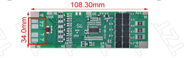
 
Doesn't look difficult to wire to me. B-, B1, B2, B3, B4, B5, B6, B+ all go to the p-groups of cells in the battery. B is for battery. P- is the negative terminal of the battery pack and goes to the load and the charging port, and P+ is the positive terminal of the battery pack and goes to the load and the charging port. Each of those need both a positive and a negative. P is for pack.

Sure there's some redundant contacts having two P- and two P+, but that just makes it easier to solder both a charge port and a discharge wire to the load to without having to put them both on the same contact or combine them into one wire and solder that on. Technically *both* P+ contacts are redundant since the BMS only switches the negative terminal of the pack on and off - so those things can just be attached to the battery positive terminal anyway.

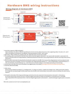
In general there are two types of BMS, split port BMS and common port. Split port can arrange the MOSFETs so the charging port only ever blocks charging and the discharge port only ever blocks discharging. This is good for regen controllers that would blow up if back charging the pack is ever blocked. It also allows not having two sets of MOSFETs on the same line just facing opposite directions. For common port BMS, the discharge/load contacts are the same as the charge ones, though, and it can block both directions. So for a common port BMS there's no need to distinguish between the two.
 
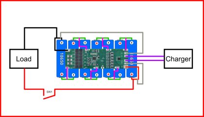
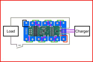
Hi Inanek, thanks for your reply and help, I think I have got my head around it, I had to draw it up to do it though, this is literally my first time at this, so is this right then ? I think I have it right !

B+ B- are connecting it straight to the battery pack but the load is being controlled by the speed controller for an e bike or in my case a simple switch to turn the lawn mower on and off.


4P7S Layout.jpg
 
I don't think that's right, no. B- is for connecting internally to the cells only. You are bypassing the BMS if you connect B- to load. The BMS needs to be able to cut off discharge if the cells hit low voltage cut off. It does this by not allowing current through from B- to P- when in that situation using MOSFETs. So load needs to be connected to P- to benefit from the BMS' functionality.
 
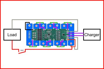
Thanks Inanek, I can see that now, OK I think I have it now. is this diagram correct now ?

Cheers

4P7S Layout_V3.jpg
 

Attachments

  • 4P7S Layout_V2.jpg
    4P7S Layout_V2.jpg
    1.1 MB · Views: 3
Last edited:
Sorry I have no knowledge of how to wire a BMS. I would start by reading the instructions.
I cant find ANY info anywhere as to what it is and how to wire it up
What is name of manufacturer? Model number? Did BMS come in a box? Any writing on the box? Did you buy BMS on the internet? Link to where it came from. Writing on the circuit board?
 
Sorry I have no knowledge of how to wire a BMS. I would start by reading the instructions.

What is name of manufacturer? Model number? Did BMS come in a box? Any writing on the box? Did you buy BMS on the internet? Link to where it came from. Writing on the circuit board?
It's an aliexpress cheapie, the instructions were incomplete and badly written but I have it worked out now, it's actually very simple but my first time doing anything like this, the wiring diagram directly above is correct now, your comment is good next time I have an issue I'll include that info with the post.

Cheers
 
If you put manufacture, part number and link to aliexpress ad, here on the internet, it might help others with the same BMS confusion.

If it smokes? You got a problem.
 
Hi Everyone, And Hi from the Blue Mountains In Australia :)

I'm new to Battery building and I've just found this site and it certainly is the answer to my prayers about battery packs
So I've been researching the subject and have gathered all the stuff I need to build my first pack but I'm now stumped as to what a Split P-P+

I'm building a 7S pack for an electric Lawnmower that used to run on Lead Acid Batteries, it's a 20 year old beast with a huge Brushed 500w motor in it

So I have a question that is probably obvious to the experienced but a mystery to me what is a Split P- P+, I have a BMS that has that and I cant find ANY info anywhere as to what it is and how to wire it up, here is a pic of the board I have and in the red box the pads in question, hopefully someone can help me out, when I put a multimeter on it the P- pads are actually connected as are the P+ pads and the PCB looks like it is as well

Any help much appreciated
CheersView attachment 385101


Looks like a common port bms:
1772310470316.jpeg
 
Back
Top