Stresses on bike frame after modification? Simulation etc.

Sellick

10 W
Joined
Oct 18, 2013
Messages
69
Hi everyone, my current ebike project is part of my university dissertation. I'm planning on cutting my frame downtube and welding in a piece of box section to store my batteries and motor. Aside from SolidWorks CAD simulation, is there any way I can calculate stresses and other technical data for this? Obviously I want to say that it hasn't weakened the frame, but I need facts and figures to back this up. Also, I have the option to weld this part of box section to the top tube as well, but I don't know what affect this will have (I don't know how much the top tube and down tube deflect independently under load, and whether this would prevent that, for example?

Any help would be greatly appreciated! Thanks very much
 
You can use Ansys Simulation for the stresses. There is a bicycle tutorial for ANSYS inthe web I think its Univerity of Alberta.
Besides you can compare the stiffness of the downtube before and after.
You could do this with a manual calculation its actually a good idea (if its just a section that you want to change and not the whole downtube) to use a similiar stiffness for your battery box compared to the downtube before. Stiffer downtube might result in more stress at the connection points (headtube BB)!
 
I try many CADs for simulating structural mechanics, before I wrote my Tensoid
Simulating mechanics can be 2 kinds:
1) simulate one isolated body (deformations, stresses), best CAE is COMSOL 4.3b
2) simulate multiple bodies with collisions and deformations (explicit dynamics), best CAE is ABAQUS 6.13-1.
its best if you want save time.
 
Thanks very much guys, both really good replies. I would love to use calculations too. I like the idea of just comparing the stiffness of the downtube before and after, but I want to see the effects of other modifications; adding a rib in my battery box, for example. It is just a section of the downtube, but it is a little more complicated than that. I'm just trying to draw up my potential designs on solidworks. I will upload some screenshots on here when I'm done to give you a better idea of my design!

Thanks very much
 
If you have solidworks CAD you may well have COSMOSexpress built in.
You can only FEA a single part and have little control over meshing, restraints & loads, but I find it's often usable, worth having a go.
 
A simple comparison of the new box tube to the original tube in terms of static bending and torsional rigidity should suffice here. No need to get into space program R&D on it unless you want to really study the joining design / gussets and fatigue /life issues on the bike. Unless you are adding to tube lengths and making butted areas (tubes further apart) smaller, you will not be effecting the other tubes in the frame much if at all.

One thing I would suggest is to show how the stresses from added weight and power will be resolved in your modifications, and over build those areas in the frame that show the higher stress in simulation or with simple calculations. May not be as elegant, but with the added weight and speed, you will want added safety factor built in. If you get too deep into the simulations, you will most likely come to the conclusion that a standard (even a heavy duty one) bicycle frame will be not suitable for aggressive use without having a relatively low rider/ motor / battery weight limit without significant redesign. Either way, you can address that based on your design criteria. Best wishes.
 
I really appreciate the response, thanks very much everyone! Here is a link to my progress thread:

http://endless-sphere.com/forums/viewtopic.php?f=28&t=55515

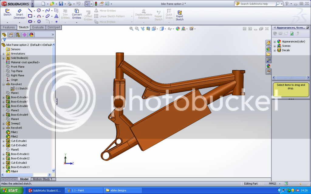
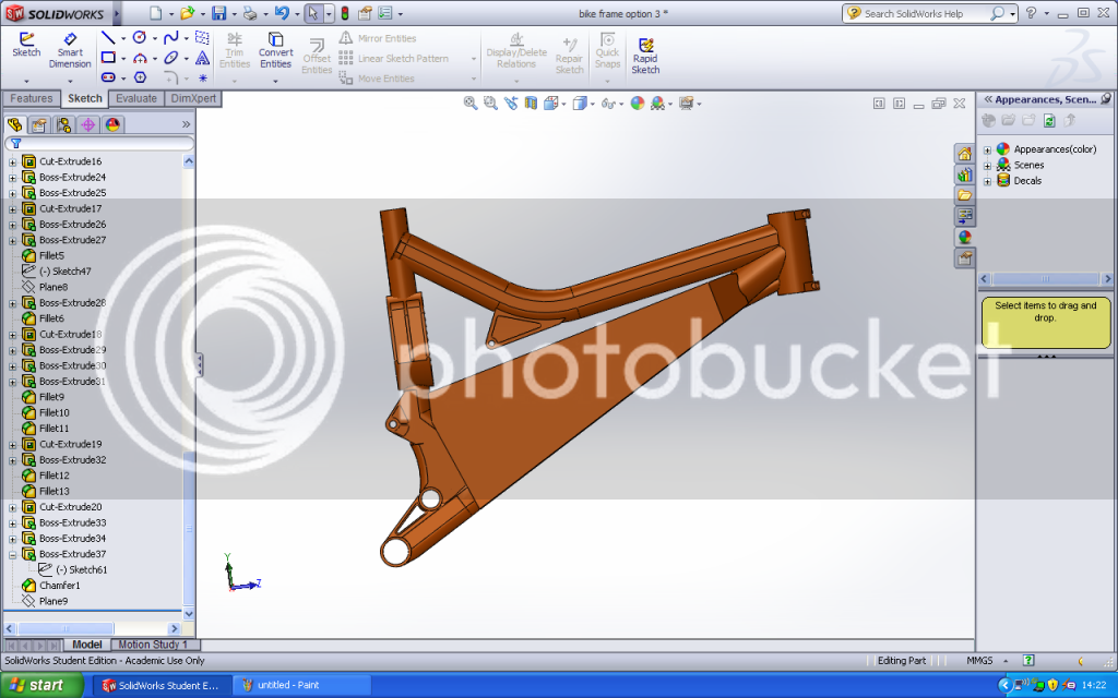
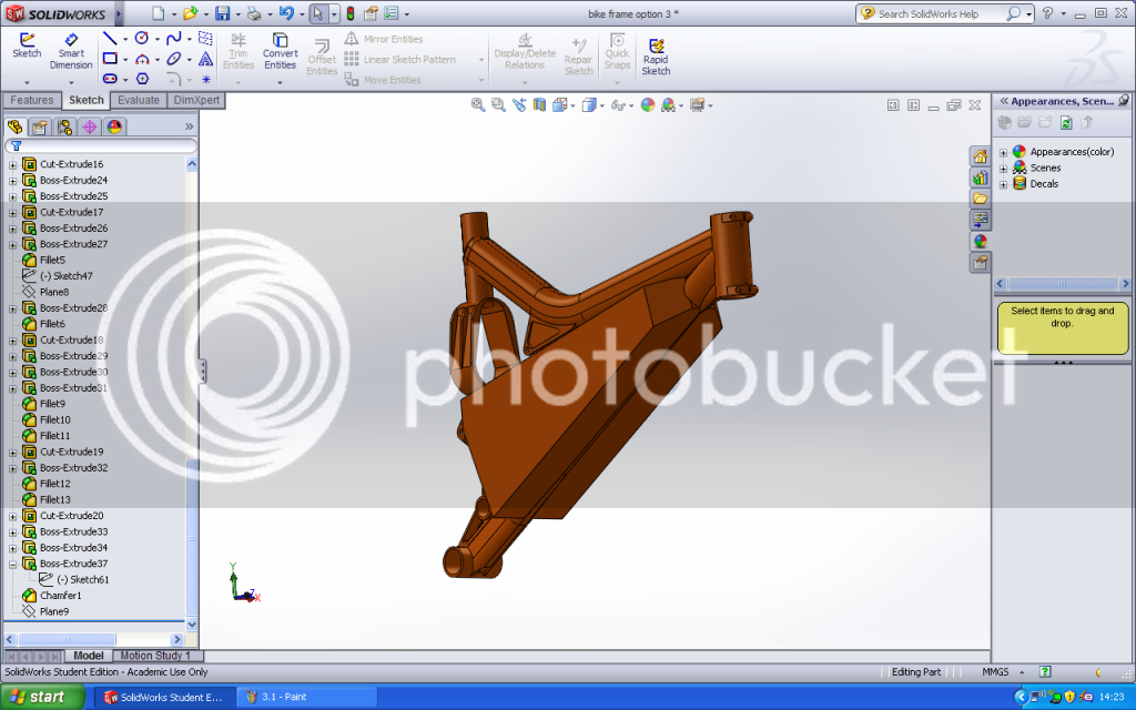
This is my frame modelled in SolidWorks


I was originally thinking this:


Although it interferes with the top tube. This moves it down (although still very close), but looks worse and gives less ground clearance:


And this is the ultimate design, although it's a lot more welding (I was going to use square box for the other designs):


So it seems it not going to be such a simple analysis. I need to speak to the guy who will be welding it to see if he can do the final design! I will keep this updated and also test it in Solidworks, but I would really like to be able to include some calculations and actually show some thought went into it!
 
Great modeling. Your most of the way there. Now you have to build it. :p

Some feed back. On the last version, I would connect the battery box to the top tube at the front shock mount and continue the box overlap/ skin all the way to the head tube. Also leave as much of the down tube present as you can to weld to. You don't want stress concentrations mid ship. You may want to add (internal tube) thickness to the down tube in the joint areas at the top (if you don't continue to the head tube) and bottom of the battery box where they meet for a few inches or blend them a bit less squarely. Large weld fillets at a minimum everywhere the box meets the thin tubes. If you are making this from sheet, you will have corner bend radiuses or corner welds that will change things significantly. Depending on your fabricators tools, it will solidify what you can do and you can then model it more exact.

cheers
 
Thanks speedmd! I modelled the frame accurately, but I just extruded the box parts out to see how it would look. In the bottom design (hopefully the one I will go with) I was planning on cutting out the dowtube completely (apart from obviously where it meets the head tube and bottom bracket). I really appreciate your input! Adding internal tube at the joints is a great idea. I have no idea what thickness material to use for the added section! I will draw it all up properly and do some analysis on it. I also need to cut a large side panel off to be able to fit/remove my batteries, and fit my motor and gearbox. I have no idea how to do this yet! Thanks again!
 
Got a few ideas for the side panel. I've realised though that it does definitely need to be heat treated. I believe the frame is 6061. I can only really get plate in 6082. Is it still just a simple (relatively) heat treatment process because the two are pretty similar? Also not sure how it will work out because the frame tubes are very thin, and the plate will be thicker. Called a place today and assuming it was all 6061 (I didn't realise this wasn't really possible), they quoted £100 as long as they could put it in with some other stuff. Is that a reasonable price? No idea what to expect to be honest although I understand that it can be a tricky process.
 
Hi Sellick

I would shop for 6061 t6 if your frame is made of that for ease of welding. 6082 looks like a expensive option for only a minor gain in strength.
http://www.aalco.co.uk/datasheets/Aluminium-Alloy_6082-T6~T651_148.ashx

Heat treated sheet is most likely the best to use and most widely available. Some comparisons of tempers. http://www.ligo.caltech.edu/docs/T/T050171-01.pdf

Some welding basics to study on. http://www.intechopen.com/download/get/type/pdfs/id/24034

Once you get a handle on it, look into weld zone solution heat treatment which will bring back plenty of strength in the heat effected zones. You can do a fairly good job with a torch and heat crayons. I would also not go with plate thicker than twice the tube walls as a general rule. Anything is possible with the right welder doing it.

Cheers
 
On a typical bike, most of the prime relastate is used up. This leaves you with the problem of adding parts that can't be significantly modified.

When I built my Ebike I started with the battery and motor. I built the battery box and drive area and then figured out how to add the bike! It may sound like the long way around but shocks and seat posts can take many forms.

One thing I found was aluminum may weld nice but there is a big strength loss very close to the weld. It took 3 tries for me to get a rear swing arm that feels right. I just finished #3 so I haven't proved it works yet. My fingers are crossed. The rest of my frame has been solid.

If your welds fuse thick base metal to a thinner frame section there will be a lot of stress right at the weld. Plus the bike frame will be weak in that same place from the heat. Not to mention how difficult it is to weld thin aluminum to thicker aluminum.

A proper re-heat treat I would assume will fix most of this. I haven't explored this for myself.

My build thread: http://endless-sphere.com/forums/viewtopic.php?f=6&t=52793
 
Thanks again speedmd! The issue is that I can't seem to find a decent supplier for 6061 plate in the UK? I've read into the welding quite a bit. I know it needs to be solution heat treated after welding, and I don't fancy doing it myself! I know you could potentially use a torch for good effects, but you then need to age it, and I don't have an oven to do this in.

I cut a chunk out the downtube today and it's 2mm thick. My issue is that I want to incorporate motor mounts/supports into the sides of the box, so they will need to be at least 6mm thick. Top, bottom, front and back (where it meets the original downtube) can all be 2-3mm I guess, depending on stress analysis results. I can mill the perimeter of the side panels so they match this thickness too. I need to get a final design fully finished, tested in Solidworks and done tomorrow so I can strip the paint sunday and send it to the welder monday! Will be shipped straight from the welder to the heat treating specialist, then back to me (by which time I'm hoping to have all other aspects of the build completed).

Joe T., I like the frame design! I wanted to keep the geometry of this frame so that I kept the handling and suspension characteristics (pedal bob, head tube angle etc.). And you're right, I don't know a precise figure, but I believe aluminium loses around 70% of its strength around the weld. That's why I've decided heat treatment will be essential! Hoping to add my box section, but maintain almost the same strength of the original frame.
 
I would use 1/8" sheet which is common. 3mm is virtually the same stuff. Loads of it as drops available state side. I would not use 6mm plate as it would be a huge waste of material. For mounts, use press in nuts.

Clinch%20Nuts.jpg


For heat treatment, simple heating will bring back some of the strength (heating is referred to as artificial aging), but plan on loosing at least 30% of the original material strengths and compensate for that with your design. I would not consider re heat treating the entire frame unless your doing much welding in many more areas. One of the things to consider is adding bulk heads at the cut off parts of the down tube. Your sheets would be welded to these through staggered window cutouts and then continue on to overlap and attach to areas /tubes beyond the cutoff areas where the frame does not see much flex / strain. You would be making little triangle shaped boxes of sorts and not rely only on the one area of welds. Even if you use a different alloy sheet, just be careful you use a compatible filler material and make fillets as large as you can.
 
I want to incorporate bearings in my mounts, and chain tensioners. I've got access to the CNC machine so it will be a waste of material, but it should demonstrate some good skills for my dissertation. I understand about the heating, but I don't have an oven. I could do the high temperature then quench, but I understand this weakens it.

Why do you say not to re heat treat the entire frame? I'm sure I read this somewhere else, but it didn't give a reason.

Also not quite sure what you mean about the triangular boxes, but I will investigate more. The welder uses 4043 filler wire.
 
Hi Sellick

I would not do the entire frame unless you fixture it. Too many residual stresses and they may force a change in shape on you. Depending on the tubing/ previous heat treatment, you could also weaken it a bit in other areas. The paper I linked before touches on over aging a bit. I would torch the heat effected zones of your welds 300-320 degrees c for 10 seconds or so and check its hardness / resilience on the scrape sections you have cut out first. If your getting good hardness and resilience I would do it by hand.

Hard to explain the shapes without drawing it out. The small ends of the battery box would be made in more of a pyramid shape (pointing away from the battery compartment) rather than triangular, with the remaining sections of the cut tube coming though the ends center and continue all the way to the inner wall/ bulkhead of the battery compartment.
 
What makes aluminum difficult to weld is the fact it dissipates heat very quickly. Hence it takes a tremendous amount of heat to get the pieces to melt. The welder needs to be set to weld the thickest part of the job 6mm. This setting may be way overkill for the bike frame @ 2mm

IF you have to weld thin tubing to a thicker base what you run into is over heating the tube before you get the thicker plate hot enough to take a weld. Machine your 6mm plate closer to your tube thickness, just where the weld needs to be. This way both the tube and plate will take the heat evenly. What is killing the strength is the heat from the weld. If you can get the two pieces welded quickly there is less heat absorbed into the frame.

The picture below is where the dropout mount welds to the swing arm on my bike. At least the basic idea...
 

Attachments

  • sample.JPG
    sample.JPG
    21.9 KB · Views: 2,074
Speedmd, thanks very much again. I will read up on over ageing, and ask the specialist what they think. I'm just not confident or comfortable doing it myself, and don't really have the equipment.

Joe T., as already stated, that's what I plan to do
 
Back
Top