alsmith
100 kW
I remember seeing a wiring diagram for switching between series and parallel connection with a changeover switch but can't find it now- can anyone please point me to it?


dnmun said:but the controller is not able to cope with doubling of voltage like that.


fechter said:It's certainly possible to make a controller that will work over that kind of voltage range.
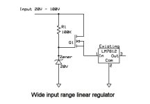
The limitation is usually in the voltage regulator part of the controller. Fixed resistors to drop the voltage won't have a very wide input range. A linear pre-regulator would be much better. Most chinese controllers could be modified to work from about 15v to the maximum rating of the FETs/caps (60 - 100V).
Below is a circuit I've used on several projects. This would take the place of the power resistors feeding the 7812 regulator in the controller. Q1 is almost any FET with enough voltage and current rating. I used a FQP6N40C in the Zephyr circuit. These can handle up to 400V.
Depending on your maximum voltage, the FET may get pretty hot and need a heat sink.
The same circuit can be used with a Darlington NPN transistor, but R1 will need to be lower, like 15K and will tend to run hotter.
alsmith said:Would this circuit work? I'm trying to keep it simple but when the batteries are connected in the two parallel diodes fitted for series are still connected.


fechter said:You would only need the diodes if the batteries have an integrated BMS with active cutoff. Even then, you would only need the diodes across the batteries.


chilledoutuk said:The question is what is the max current handling switch available to do this?
