
auraslip
10 MW
- Joined
- Mar 5, 2010
- Messages
- 3,535
So... building a high powered charger from server power supplies is pretty awesome. Except that I can find no easy way to monitor what's happening on the dc end because the turnigy watt meter only goes up to 60v.
A long time ago DOC showed a great way to use a $15 kill-a-watt to monitor up to 15a (or 30a with two) using a modded kill-a-watt.
The problem is that the PCB on the newer ones is different.


The 5v regulator on this PCB is the little 4 leg SMD on the middle left of the board with the IC. The regulators data sheet is attached.

From the point which I soldered the wires feeds the 5v regulator. It reads ~15v when hooked up to a 110v source, leading me to think I can use a 12v psu to power this.

I manged to get it running with the 9v battery and a 4s lipo pack on my tester. It's within .2a of my multimeter which itself might be quite inaccurate.
I'm not quite ready to pat myself on the back yet as there is some very strange issues involving the display and perhaps software.
A long time ago DOC showed a great way to use a $15 kill-a-watt to monitor up to 15a (or 30a with two) using a modded kill-a-watt.
Postby Doctorbass » Tue Jul 31, 2007 8:56 pm
TylerDurden, I have something for you:
Here are some pics of my first power meter:
using P4400 kill-a-watt.
ALSO!
Here is how to calibrate it (setup menu trick)
-----How to calibrate the Kill A Watt-----
Somehow set up a 110VAC 10.0A load. Probably best if it was resistive.
1. Push "Volt" and "Hz" at the same time to get "oPEn" on the display.
2. Push "Watt" until "C110" is displayed (C220 calibrates it for 220VAC).
3. Push "Hz". This is like an 'enter'. That should tell it you want to
calibrate for 110VAC
4. Push the "Watt" button until "SAVE" is displayed.
5. Push "Hz" to enter the calibration. The meter seems to think for two
seconds (probably doing the calibration) and then the voltage and current
will read true.
:wink:


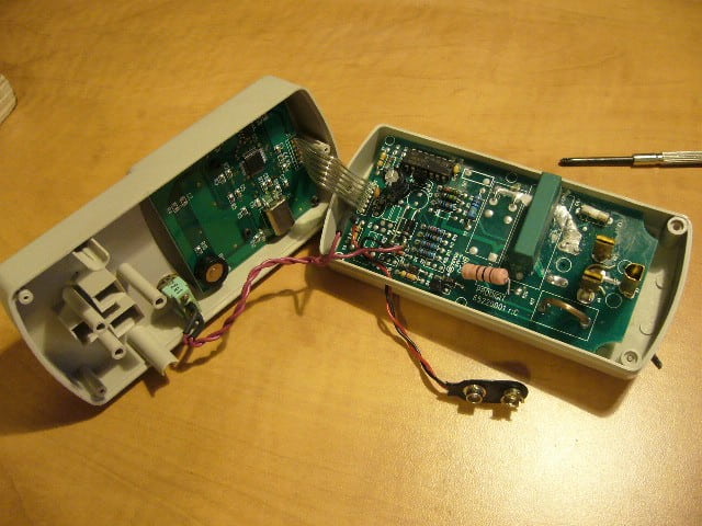

The problem is that the PCB on the newer ones is different.
The 5v regulator on this PCB is the little 4 leg SMD on the middle left of the board with the IC. The regulators data sheet is attached.
From the point which I soldered the wires feeds the 5v regulator. It reads ~15v when hooked up to a 110v source, leading me to think I can use a 12v psu to power this.
I manged to get it running with the 9v battery and a 4s lipo pack on my tester. It's within .2a of my multimeter which itself might be quite inaccurate.
I'm not quite ready to pat myself on the back yet as there is some very strange issues involving the display and perhaps software.