Using the Meanwell S-240-48 as charger

rkosiorek

100 kW
Joined
Jan 18, 2007
Messages
1,770
Location
Belleville, Ontario Canada
I am trying to convert a Meanwell S-240-48 power supply into a CC/CV charger. It is very much differeent than the S-350 series chargers that have been discussed in other threads.

first of - the input section uses a STR83145 voltage sensor to automatically select the input volyage range between 88-132VAc and 176-264VAC. there is a very fancy EMI filter and inrush current limiter.

second - the PWM is based on the TL3843 Current Mode controller chip. current limiting is performed by this chip and is stricly a Hiccup mode protection limiting the input current to the primary coil of the transformer to a safe level. I don't see an easy way to use this for a CC control.
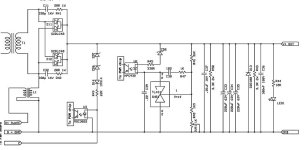
s-240-48 output.jpg

third - the secondary of the transformer feed a fairy simple rectifier and filter section.

forth - Voltage regulation is through a fairly conventional control loop using a TL431 as a shunt regulator controlled by a voltage divider and driving a transistor output HPC932 optocoupler used in the linear mode.

fifth - protection for Over Voltage (ZD7, ZD6)and Over Temperature (separate fan board) is provided via a Triac output Opto Coupler MOC3022. I guess turning on it's LED will force the PWM into hiccup mode.

so i see that if i reduce R48 from 1.5K down to 1.1K i will be in the right range for approximatetly the 58.5V output i am looking for to charge 16S LiFePO4 packs. what i can't figure out is a simple method to implement CC.

any Ideas? any way of using something as simple a Tiberius's single transistor current limiter?
 

Attachments

  • tl3843.pdf
    529.1 KB · Views: 65
  • s-240-48 output.pdf
    17.1 KB · Views: 80
  • s-240-spec.pdf
    310.4 KB · Views: 65
This is the same sort of circuit they are using on the SP series, where the only thing used for current limiting is the hiccup mode on the front end. One of the things that Richard and I did with the new CellLog-based charge control unit was to pull out the MeanWell current limiter function, and put it on its own PCB that can be mounted right to the terminal blocks on the front of the supply. Here's what the board looks like:

View attachment MW Current Limiter-v4.1.6.png

It is pretty basic, with a shunt-based current measurement/comparison opamp section, that feeds the same PWM-controllled FET output circuit we've been using for "throttling" in all the BMS circuits. There is a trimpot that can be used to adjust the current limit from about 2A to a max of about 20A.

-- Gary
 
Great job GARY!
-Mike
 
thank you. that looks very interesting gary. can you post a little more information please. such as a schematic and some parts values? at a quick glance it looks like Q1 is an amplified zener for approx 15V output. U1 is likely a 78LXX type of regulator and there are 3 op-amps. i see you are using a 5mR sense resistor and control is supplied by a pair of mosfets.

If at all possible i was trying to avoid adding a bunch of power stuff and instead just try to add a second feedback loop to control the HPC932 optoisolator. i'm hopping i can find a way to use fewer parts.

but i'd still like to your your schematic. thanks

rick
 
i thought about using a "BRUTE FORCE" style current limiter using a power transistor and a TL431 shunt regulator.


but then i was thinking that i would need to heatsink that transistor. it will dissipate 80W or so when charging an empty pack with that i could use it to reheat pizza, warm up my coffee, etc. and i'm not sure the TL431 will sink enough current to drive the 2N3055.

I need something much more elegant.

rick
 
well after thinking about it a little and not getting any ideas from anyone else, i think that i am going to try to modify my output section to provide a CC/CV output.

i need an output of 58.5V and a current limit of 4 amps or so. i have a few samples of the TSM101 Voltage Supervisor that i have been itching to try in a circuit. so here goes.

first i need to strip out the parts i will no longer use from the original power supply. the revised schematic

s240-48 mod2.jpg

then i'm going to wire up a small circuit on a piece of perfboard that will provide feedback for both voltage and current.

CC-CV Conversion1.jpg

initially i was planning on building a separate low voltage regulator as well. but then i found that the small fan board already has one. so i am just going to tap into that and solder some wires to the boards to add my small circuit.

SVR1 is a trimmer that should allow the output voltage to be trimmed between 42 and 62V. SVR2 is a second trimmer that will allow the current limit to be set between 1 and 5 amps. that is if my calculations are correct.I'm going to leave the over voltage protection intact in an attempt to avoid destroying the balance of the circuit.

parts are ordered. now i just have to wait for the fedex guy in the morning before i can proceed.

any electronics experts please chime in and tell me if i made any seriously abvious mistakes.

rick
 

Attachments

  • CC-CV Conversion.pdf
    14.2 KB · Views: 71
  • s240-48 mod.pdf
    15.7 KB · Views: 53
i'm still waiting for the parts i ordered to arrive. in the meantime i planned out the layout of the circuit on the perfboard. it also would work as a PC board layout. and heare it is.

complete2.jpg

screen1.jpg

the only part not on the board is the output diode. that is an optional component anyways. i just included it as a safety precaution so that the charger would not drain the pack if it is left connected but not plugged in.

the complete board is approx 1" X 2" and it should be able to fit inside of the original power supply box.

rick
 
I had a bad experience with my last 28V 350 watt Meanwell, that I instead picked up a 13.5V 350 watt and now charge my 8s1p in a 4s1p one at a time method.
I now also place a Turnigy watt meter after the PS to monitor the charging.
This works 100% great at all output voltages 10%+- 13.5v
the PS does not hiccup, and the fan comes on only when pushing 20+ amps into the battery.

So, I couldn't help it, I had to try charging without the Turnigy watt meter inline again..
I set the output voltage to a moderate 13.9V output.. my battery cells were resting at 3.29-3.3v
As I expected the PS started to make noises after 5 seconds, and I quickly disconnected the connections.

So.. what is the deal here.. does the watt meter have a diode or something totally different to keep the battery from frying the PS ??
 
rkosiorek said:
well after thinking about it a little and not getting any ideas from anyone else, i think that i am going to try to modify my output section to provide a CC/CV output.

Sorry, didn't notice this thread at first. The circuit looks good to me. Of course a variety of things can go wrong when mucking with feedback circuits, so have to try to be sure.

Let us know how it goes. I have to dig out my SP320 to see if it can take the same type of mod.
 
after Canada Customs finished putzing around with my order for a week i finally got the parts to make up the little TSM101 feedback circuit. i built one up on a 1 by 2" piece of perfboard. but i have not had a chance to test it out yet.

i will post a picture and progress as soon as i can.

rick
 
Why aren't people using the HLG-240-48's etc? (they are CV CC for LED arrays) - all the hard work is done!
 
HLG-240-48 seems 240 watt compare to S-350-24 gives 350 watt only cost me 32 dollars on ebay.


heathyoung said:
Why aren't people using the HLG-240-48's etc? (they are CV CC for LED arrays) - all the hard work is done!
 
heathyoung said:
Why aren't people using the HLG-240-48's etc? (they are CV CC for LED arrays) - all the hard work is done!

good find. but i have never seen one listed on ebay in Canada or the US. but i will have to add it to my watchlist for the future. new cost on these from distributors is over $120USD. and i would still need to change one resistor value to get the output voltage up to 58.4V that i need. another plus is that these arre already in a partially weather resistant box.

I was sort of hoping the S-240 series of power supplies would be easy to add or adjust the CC current. but such is not the case. i have 4 of these S-240 series supplies on hand and it seems a shame to waste them. so modify them i must.

rick
 
after much experimentation i got the TSM101 circuit to work. just when Fechter posts an easy solution in the "switch mode power supply mod" thread. makes me wonder why i chose such a complex method to go about doing this mod.

Using the TSM101 requires considerable surgery to the power supply as it replaces the Voltage control and adds a current control loop. Fechters single op amp circuit is just an add-on that leaves the power supply intact. it is simple enough that i think i'm going to try it.

rick
 
Inspired by the recent developments on the "Power Supply mods" thread by Fechter and others i adapted the design to fit the parts i have on hand. the ciruit is very simple and only requires that 4 wires be attached to the existing circuit of the Meanwell S-240-48 power supply. i'm going to test this a bit more over the weekend. but the inital tests are very promising.

auto shut off cc-limiter.jpg

s-240-48 mods.jpg

rick
 

Attachments

  • auto shut off cc-limiter.pdf
    14.2 KB · Views: 49
  • s-240-48 mods.pdf
    17.1 KB · Views: 53
Back
Top