zombiess
10 MW
This is a simulated comparison I performed on Si vs SiC MOSFETs for a buck inverter I am designing. I thought that others might enjoy some of the info I got from performing these. The original goal was to simulate the junction temperature of the MOSFET after calculating it's losses. This is a little trickier than it sounds as it has to be through an iterative process. Once a Tj is found, the simulation must run again to calculate the losses at the higher junction temp, which then needs to be run again. I found through trial and error that 10 iterations was a good amount to achieve a stable Tj.
Many of you have heard me say that there is more to losses than the conduction loss. Conduction loss is determined by the RDSon of the device.
Choosing a device for your inverter depends a lot on what ranges it will operate in. Bus voltage, switching freq and how dynamic the load can alter your choice in device to meet a goal.
All of the heat sinks were setup at the same and manufacturers spec sheet values were used. Many of the losses in the device vary with current and junction temp. To account for this, 2nd and 3rd order polynomials were used instead of linear fitting to maintain accuracy. The formulas were calculated by performing a curve fit from the datasheets values. Not all the manufacturers datasheets have the same parameters, so this comparison was customized to these devices to make the outcome as accurate as possible while trying to avoid assumptions.
Only the main losses were simulated, switching energy loss, conduction loss, diode forward drop and diode reverse recovery.
Feel free to ask questions and I'll do my best to try and answer them. If you would like to see a comparison of these two devices performed, post up what settings you would like and why. I'll try to get the results posted so we can discuss them further. Unfortunately I do not have much time to compare different devices than what I have here due to the time to enter the data into the simulation and the datasheet research to get it as accurate as possible.
I'm not sure what the accuracy is of this to real life. I would hope it is withing 10%.
And now for the graphic nerd porn I promised :lol:
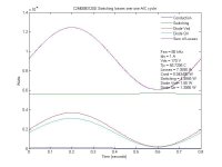
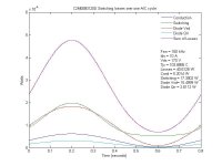
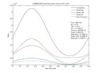
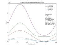
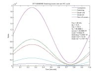
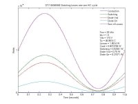
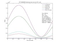
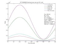
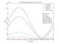
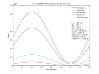
REMEMBER when reading these graphs that the losses were calculated at EACH PWM PULSE on a 1Hz sine wave. That is why there is a sinusoidal shape to the losses. To get the total, you need to take the integrate the area under each curve, that is what was done in the text showing the total of each curve.
First up SiC at 1A and 10A @ 170 VDC Bus
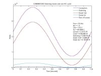
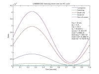
View attachment 23
View attachment 22
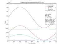
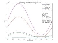
View attachment 18
View attachment 16
View attachment 14
View attachment 12
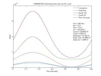
Si MOSFET 1A and 10A @ 170 VDC Bus
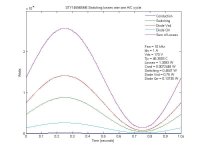
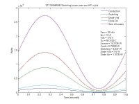
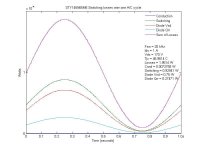
View attachment 5
Many of you have heard me say that there is more to losses than the conduction loss. Conduction loss is determined by the RDSon of the device.
Choosing a device for your inverter depends a lot on what ranges it will operate in. Bus voltage, switching freq and how dynamic the load can alter your choice in device to meet a goal.
All of the heat sinks were setup at the same and manufacturers spec sheet values were used. Many of the losses in the device vary with current and junction temp. To account for this, 2nd and 3rd order polynomials were used instead of linear fitting to maintain accuracy. The formulas were calculated by performing a curve fit from the datasheets values. Not all the manufacturers datasheets have the same parameters, so this comparison was customized to these devices to make the outcome as accurate as possible while trying to avoid assumptions.
Only the main losses were simulated, switching energy loss, conduction loss, diode forward drop and diode reverse recovery.
Feel free to ask questions and I'll do my best to try and answer them. If you would like to see a comparison of these two devices performed, post up what settings you would like and why. I'll try to get the results posted so we can discuss them further. Unfortunately I do not have much time to compare different devices than what I have here due to the time to enter the data into the simulation and the datasheet research to get it as accurate as possible.
I'm not sure what the accuracy is of this to real life. I would hope it is withing 10%.
And now for the graphic nerd porn I promised :lol:
REMEMBER when reading these graphs that the losses were calculated at EACH PWM PULSE on a 1Hz sine wave. That is why there is a sinusoidal shape to the losses. To get the total, you need to take the integrate the area under each curve, that is what was done in the text showing the total of each curve.
First up SiC at 1A and 10A @ 170 VDC Bus


View attachment 23
View attachment 22


View attachment 18

View attachment 16

View attachment 14

View attachment 12

Si MOSFET 1A and 10A @ 170 VDC Bus


View attachment 5


