What Should No-Load Phase Wire Volts Be w/67v Batt. Volts

Joined
May 25, 2009
Messages
20
Location
Yichang, Hubei Province, China
This is one for the more knowledgeable ones than myself.

My Chinese bred 'Cargo Bike' is reading 37 volts, full throttle, no load (wheel spinning), at each phase wire (voltmeter positive to phase cable and the negative going to battery ground).

The battery volts are running at 67, sagging to 66 ('snaps back to 67v when I back off the throttle) when I do this. The controller has a soldered up shunt and all of the cables from the batteries, all the way back 'into' the motor are 10ga or better. The controller traces for the + & - and fets are all bolstered with 14ga wire fattened with generous solder. The controller itself based on an NEC F9234 IC, but looks damn near like an Infineon 9 FET (FET's are the 75NF75).

What should I actually be getting for phase output voltage from the controller(hell, maybe I'm even measuring it the wrong way). I was expecting a voltage around 80% of battery (48-53v).

Gringo
 
what drunkskung says is true.

the phase current is not only switched at the PWM frequency. but each phase is only on 1/3rd of the time. no way a simple meter could read that accuratetly. you would need an oscilloscope and measure the peak values.

the peak voltage of each pulse should be close to the battery voltage, less any sag from the current draw and losses thru the series shunt and the Rds of the FET.

for a "Gestimate" only - take the reading from your DVM of 37 and multiply by the square root of 3 or 1.732. that comes to about 64V and is close enough for simple diagnostics.

rick
 
Thanks Guys!

Yeah I know the phase are pwm.

Unfortunately an O-Scope is outta the question. English teacher's salaries suck and nobody in my part of the bushes would know what I was talking about. I'm lucky to have sourced hi-output LED's and heatshrink tubing here.

I had a mishap with a Hall sensor . . . . knocked a leg off it when my hand slipped pulling big phase wires through the motor. I couldn't beg borrow or buy a Hall sensor here if my life depended on it (ended up repairing it by butt-soldering a piece of 24ga onto the little dot of lead in the body and super gluing a plastic bead to that and the body of the hall . . . it's been running every day since . . . major laxative effect).

I could rig some kind of 'peak detector' with a diode and a cap (robbed from a junk computer PSU) I suppose to use with the DVM, but I was just wanting to find out how tight the PWM was in this thing, if I was getting everything out of it? Always looking for an extra 10kph to blow around the Chinese taxis you know, plus I have the wifey butt factor 'on the back' to haul around with me every day!

MarkIMG_0789xsml.JPG
 
Yes, a diode and a cap would work. Also remember that the polarity between the phase wires is reversing with each cycle. It would be better to measure any phase wire from the battery negative. The peak ought to be equal to the battery voltage. It might even be a bit higher due to inductive kick during parts of the cycle.
 
you gotta tell us more about the bike, what size wires? is that the motor in your avatar?

you could get speed by adding another SLA on top of those 5. i converted the 9 FET infineon from 36V to 72V by adding 100V1000uF caps to replace the 63V470uF caps that were stock,and added added another resistor to the input power resistor along with resetting the LVC. i had to move the power resistors underneath too so the caps would fit.
http://www.endless-sphere.com/forums/viewtopic.php?f=2&t=10222

god knows all that space is just itching for more batteries to 'lower the center of gravity'. are your batteries 18Ah wide? maybe you could hang a second parallel set under that frame on each side in back.

maybe someone can mail you a hall sensor if it really is that hard to find parts. what do the locals do, besides mend the broken parts like you did?
 
Thanks for the help and kind words. Everybody here is very generous and knowledgeable.

Here's a link to what this thing is supposed to be:
http://www.madeinchina.com/2775653/P6092985/electric-bike-Load-E-bike.shtml

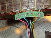
I've attached some pictures of the rewiring. Between that and the built up traces and soldered shunt I got another 5mph out of her from stock. The torque for climbing hills is better too (it's not throwing anybody into 'hyper-space', but I can pass a bus or 2 now, whereas before they'd try to squash me like an irritating little bug).

The inspiration behind this, beside blowing around 'zombie' traffic (most fun ya know) is one day the Missus and I were climbing up a steep street to one of the classrooms we teach at. Somebody did something to make me slow to a crawl at the first part of that hill so I lost momentum. When I got back on the throttle, after about a block, I smelled and touched melting phase wire insulation. Nothing shorted fortunately and the insulation cooled itself back to a fairly normal consistency after. But that was when I said OK! Out with the stupid 'telephone type' phase wire, we're going to put some real wire in this thing! The other good indicator was that the motor and controller were only ambient temp while the phase wires were frying. 'Now' the motor and the controller are only slightly warm and the phase wires are running ambient temps when I load the hell out of it.

The nice thing is that none of this has appeared to negatively effect my range that I can see. I have never had to 'opportunity charge' during the day ('though I put the charger on it 'most every night). I'm at full throttle most of the time running unless I'm caught in a 'cluster f*ck' in an intersection somewhere. On account of the windings in this motor and programming in the controller, I'm getting hellacious regen in this thing and it's weird subtle about it too. Most of the time I never feel it unless I lose like 1 light on the 4 led 'idiot light' volt meter in the instrument panel, then I feel it pulling me gently down when I back off the throttle. I've never hit the 'lvc' limit. One night I drove this sucker for almost 2 hours straight (after putting around 16km during the day), lights on and all, limped it home on 1 remaining 'idiot light, pedaling intermittently for the last 15-20 minutes only.

The only place I've really got to add anything component wise is to the seat post on back. Everything back from there is for hauling Wifey legs or butt or some sort of cargo or other (I've hauled 3 sets of small school desks and chairs, at one shot on the back of this little girl . . . looked like the 'Beverly Hillbillies' were coming to China). That space between the seat post and the rear fender is kinda reserved for future use . . . I'm thinking of playing around with a Hall signal conditioner/adjustable timing box to see if there's anything to be gained from that (that's if I can source somebody here that will actually order something or 'act' like they know what I'm talking about to get the components . . . like flip flops, buffers and such). Oh! and the seat cushions on the back fold open to make another cargo platform in addition to the ones that fold out from the rear axle area(they also act as torque arms, they're slotted onto the axle and tab around the frame).

The battery box is 'stuffed' with the 5 12v 10ah sla's (the bike was advertised as 12ah or 14ah, but when I opened it up . . .'guess what Boo-Boo'! This is China remember!). I'd have to wait for other technology to come down in price and size to bump it up to 72 or 84v. The space down low, between the down tube and the seat post contains the controller, connectors and wiring, a big ol' frame tube and the pedal and sprocket guts (I could 'maybe' fit another controller in there if I got some 'dosh' and inspiration to make it a 2wd someday).

My next little project is to add a 1.0uf 250v mylar or ceramic cap(because I have one laying around) right about center of the pcb, between the main + and - traces for the FET's in the controller to peck at spikes. I may install a fairly hefty diode inverted (stripe to positive) between those traces to help with the same issue (as with the caps on the Hall's, I haven't blown anything up yet, I'm just trying to be proactive based on experiences I've read about here). The main caps in the Controller are too close to peak volts for my liking too, rated at 80v, and if I remember correctly they're only like 890uf each @ 2 of them. I've got a couple of 330uf 200v electrolytic's in parallel on the main battery connector to the controller to help take the load off for now.

Mark
IMG_0704a.JPG
IMG_0809a.JPG
View attachment 5
IMG_0848a.JPG
IMG_0853a.JPG
IMG_0861a.JPG
View attachment 1
IMG_0874a.JPG
 
dnmun said:
you gotta tell us more about the bike, what size wires? is that the motor in your avatar?

you could get speed by adding another SLA on top of those 5. i converted the 9 FET infineon from 36V to 72V by adding 100V1000uF caps to replace the 63V470uF caps that were stock,and added added another resistor to the input power resistor along with resetting the LVC. i had to move the power resistors underneath too so the caps would fit.
http://www.endless-sphere.com/forums/viewtopic.php?f=2&t=10222

god knows all that space is just itching for more batteries to 'lower the center of gravity'. are your batteries 18Ah wide? maybe you could hang a second parallel set under that frame on each side in back.

maybe someone can mail you a hall sensor if it really is that hard to find parts. what do the locals do, besides mend the broken parts like you did?

dnmum,

The batteries can throw me around a bit from the high center of gravity, added to that, Wifey sometimes is like hauling 115lbs of 'spastic Jello' as she throws her weight around looking 'this way and that' . . . I just go as fast as I can (including the corners) to get 'gyro stability' out of the wheels.

The locals patch things together or just let them run into the ground as a general rule (they'll drive a week on a flat). The parts I need are here I'm sure of it, but a lot of Chinese have 'little guy syndrome' in if they think they have something over me . . . 'they have something I want', sometimes they'll play dumb just to 'f' me, even if it means they lose a sale. I had a sheet of paper with 4 different part numbers of 'Hall candidates' that would work, including pictures of the things and I had it all in 'both English and Chinese'. Even the electric motor repair shops played dumb, and you could see they were trying real hard to get a reaction out of me and p*ss me off (I wouldn't give any of them the satisfaction, just smiled and thanked them for their time and left).

Yes that is the motor in my avatar.

Mark
 
fechter said:
Yes, a diode and a cap would work. Also remember that the polarity between the phase wires is reversing with each cycle. It would be better to measure any phase wire from the battery negative. The peak ought to be equal to the battery voltage. It might even be a bit higher due to inductive kick during parts of the cycle.

Fechter,

Thanks! for the clarifications. Other than the basics I'm still trying to wrap my brains completely around this BLDC thing. I mostly get the one neutral/dead phase and the push pull of 2 in a cycle.

I'm just looking for nickels and dimes to pick up at this point and not leave any significant power on the table with what I've got for batteries, basic controller and motor. That and try to catch any potential reliability issues as this thing is daily transportation.

But man! I'd love to make a wye/delta box with rpm based switching. I know this sucker would hit 35+mph/56+kph on the flats and if I smoked something in it the Wife would castrate me in my sleep!

I'm reading my own posts and realizing how schizophrenic I'm sounding. Faster! No! run everyday! No! faster! No! It's got to run every day!

Too much caffeine.

Tomorrow I'll solder up my peak detector to play with.

Mark
 
the stock red hall supply wire was ok, 14G is a little overkill, just a few milliamps of current, but the 10AWG phase wire is mega, and soldered battery connections too. the concern over a floating ground is true, but the current you are sinking into that ground is not gonna cause a voltage delta on the hall sensors. i woulda left that all stock. but you pushed alotta wire through the hole.

the goldenmotor 48V regen controller had some 62V zeners with a 3W, .2ohm wirewound power resistor between the S/D busses like you mentioned, because they added regen to the board and the board was already limited by the 63V470uF caps and they figured it was cheaper to add the zener to protect the FETs and caps from the regen spikes. if you put a zener in there, you need to add some resistance in series, if only a little to keep from burning up the zener i would expect. they all still blow up, i think duane had blown 6 or more. but if you don't do regen, not worth the worry imo.

http://www.endless-sphere.com/forums/viewtopic.php?f=1&t=9746

not to worry until you get to 72V nominal since the 75V FETs seem strong enuff to run up there around 75-80V and the breakdown voltage climbs with temperature too i think. if you have 80V caps already you may be able to try 72V with the current setup, the wife may start kicking you if you blow the controller though.

i saw the little ceramic caps on the hall leads, there should not be noise there since it goes through 2 regulators and has a buncha caps to stabilize the 12V and 5V rails so the hall power should be the cleanest on the pcb. i still am impressed you got that dead hall sensor working. tell the chinese part supplier refusniks about that and see if they are impressed. i assume they act that way because your chinese is not the local dialect. people in the south in this country get that way when they hear someone speaking yankee, or if you use a brain to consider alternatives to the presumed stupid solution for anything. the response is always "my daddy did it this way and his daddy before him..", i think you know what i mean.

but it has pedals so it's a bike, looks like nothing but single speed though. i doubt if the delta is gonna change your top end much since there is a lotta mass. wait and see how many blow their controllers up first.
 
Dnmun,

I've got limited 'old school' electronics knowledge and me old dried up brain says "Skinny wires-inductors(unless there's a high resistance on them like a thermistor) . . .fat wires-capacitors". That and the pcb design hammering I got way back when about always put a small cap across the power pins of every IC or every other IC if you can.

2 things on the Hall's having caps though: They're a long long way from any pcb and the wires have to run several inches right next to the phase wires, plus the inside of a BLDC has got to be a nasty environment as far as noise goes. I was worried about false triggering and the havoc that could cause.

Then if you look at most application guides for either the Hall's or for the Controller IC's themselves they'll specify running .1uf ceramic caps on all the Hall power leads and(my bad I didn't do this part) a 10uf on the joined + and - power wires for them nearby. I have 10uf 16v electrolytic's but I wasn't sure how much 'heat' the motor was going to make after the wire fattening and the current shunt soldering and I didn't want to tear the motor apart to just replace a stupid dodgy cap. I know now from running the dog out of it it'd be a non-issue, the thing runs tepid at best. I could have even run the cap in the loom but the bike was already down for almost 4 days as it was (spare time is slim) and I just needed to get it back on the road . . . time to shoot the engineer as it were, so I said screw it.

I couldn't figure out why the IC manufacturers were specifying those caps on the Hall's but they are never ever implemented in any of the motors that I've seen. And then I was really surprised that I couldn't get a phone charger 'wall wort' of any kind I have here to properly supply current to all 3 Hall's at the same time to test them . . . I could do 1, but not all 3. One of the wall worts was a 6v 750ma job, and still had not enough current, so that experience and potential inductance is why I went overkill on the 14ga.(and it is running around a meter's length out from the controller to the inside of the motor anyway). So it was: "what's it gonna hurt"?

I was reading a pdf from a controller IC mfg. and apparently some pcb designers were using the 5v vref pins on the Controller IC to power the Hall sensors . . . which were causing, in many cases the Controller IC to malfunction from excessive current draw on that vref pin.

The bike is a single pedal speed yes. The only time I really ever pedal is if I get blocked in the middle of a steep incline, like a stop light and then just to get going otherwise the pedals are just 180 degree foot pegs to me.

Mark
 
I never see them put caps on the hall sensors, but like you say, it can't hurt. I figure that since all 3 sensors are powered in parallel, that just one cap located in the motor should be enough to clamp any spikes.

Some controllers have a speed limiting feature, but it is fairly rare. You might be able to detect the presence of such a feature by noticing that the speed remains constant when you start going up a slight hill. With a normal controller, the speed will immediately begin to drop.

I think your biggest improvement would come from upgrading the batteries to some good LiFePO4 ones. You could get a bit more power stuffed into the same space and save a bunch of weight at the same time. If you're cheap like me, run the SLA's until they die, then think about lithium.
Delta/wye switching looks like it should work with that motor if you decide to try it. Can you tell what the stock configuration is? It also looks like there might be enough room inside the motor for a bunch of relays.
 
fechter,

The stock config on the motor is wye. I just wanted to be pulling good torque and have a reasonable top end in wye before I even considered doing a wye-delta switch otherwise this thing would just be falling flat on it's face during the switch. It's not bad now (after the wire fattening)for what it has to carry in weight everyday.

I do see a decrease in speed with a slight rise in a road or headwind so I don't think at this point there is any purpose built speed limit in the controller. I think 'back EMF' is my biggest enemy right now. I can really feel it going down a steep incline. No amount of throttle will get me past a certain barrier and while I don't have any hard data to give you on actual speed it feels like about 40mph/64kph, that and judging by the rate I'm passing the cars around me(until they feel embarrassed about something with pedals going by them, then they go like hell to pass me back up again). It feels like a giant hand is coming out of nowhere and holding the bike back.

The decrease in speed from an incline or headwind is greatest at the upper speed and will only get to a point, then it just keeps pulling like an ox, usually much faster than I can pedal even on a relatively steep incline (I'll have a bus matching speed with me on a hill about 75ft back and I need to get into his lane to make a left turn so I try to give it some pedal boost, but no avail, I can't keep my feet on the damn pedals at that rate).

The sla's are a performance issue but like you say, I'm going to kill those before I do anything else as far as batteries. I've only discharged them big (but still above the 52v lvc) one time so far in the 3 months since we've owned this bike and I'm good about plugging it in most nights so I'm hoping to get maybe 1 1/2 to 2 years out of them. Maybe by then there'll be 12v 20ah batteries the size and weight of a paperback novel for 15 bucks each.

I'm going to play with the 30a fuse and holder in the battery box too. I don't really think I'm getting 200 + degree contact on the ends of the fuse and element heating may be adding to sla sagging. I definitely need something for short circuit protection but there may be better alternatives to glass fuses and u-clip holders(oh and I've never blown a fuse so . . .).

Mark
 
ok, i eat my hat.

i am gutting this goldenmotor which twisted off the forks and tore off the phase and hall wires, and finally proved to myself the halls were bad so i cut out all the phases wires and hall wires so i can feed larger phase wires back in and new hall sensors will be installed.

the goldenmotor has a little pcb with the halls soldered into the board and the red power trace runs across the bottom and the ground trace runs across the top from the right side, notice just to the right of the blue hall sensor lead, there is a surface mount cap connecting the red and black wires.

is there someone here on the sphere who has a stash and sells them out to others, or trade? they read 41F 817 and are 3mm wide.
 

Attachments

  • goldenmotor hall sensor pcb-4.JPG
    goldenmotor hall sensor pcb-4.JPG
    71.8 KB · Views: 1,259
Back
Top