F4P's 144mm low rpm Outrunner

F4P

10 mW
Joined
Jul 6, 2011
Messages
34
Location
Germany
Hello!

Some time ago I asked for something slow turning, high efficenicy motor in this thread http://endless-sphere.com/forums/viewtopic.php?f=30&t=53769...barly got any answers. I think there is'nt such a motor out there.

Some words to the project: I'm going to build a Human Powered Serial Hybrid Vehicle (Going from HPV to HPSHV). Generator, little storage device, and two wheel drive. I know, that this is not making any sense in terms of efficiency for a normal bike or trike. But you will later on see my points for building such a hybrid drive.

Here are my requirements:

0 - 1000 rpm 20Nm 10sec, 15Nm for 5min, 10Nm countinously

typical loadpoints are:
rpm W_mech_out Bat_Out @ 50V w/o eff cal.
300 rpm 20W -0,5A
500 rpm 50W -1A
700 rpm 100W -2A
900 rpm 200W -4A

and worst case loadpoint are:
100 rpm 150W -3A ( more 4,5A with realistic eff.)
1000 rpm -750W +15A (yeah, breaking down the thing)

direct drive for eff and weight
average power Input 200W for typical humans, 300W for trained humans :roll:
hybrid storage energy 10Wh to play with add power and recuperate and do some other nice stuff
55V max System voltage
2kg per motor, so 6kg together
peak complete hybrid drive efficiency 85%

I hopped, that I could use or adept something like Miles Inrunner. My Intension was to mount 2 inrunners in the middle of the vehicle and drive the wheels directly with a drive shaft. I rebuilt Miles Inrunner in Emetor and played with it to reach my requirements (I hope this ok ?!? :roll: ), but it didn't work. This thing was to small to mount enough magnets to achieve a usefull electric frequency, getting to long for Nm req. and finally getting unwindable.

First lessions learned: slow turing makes electric motors heavy, longer and/or bigger in diameter. Transmissions and drive shaft bring weight and cost eff. So back to school...getting more deep understanding of electric motors.
Results: skip the drive shaft, taking it's 300g weight for 20Nm application, put it into the motor. Skip the inrunner concept, make an outrunner for 48 magnet poles.
So here we are: I Need a small HUB MOTOR. Oh no...I always thought, they are big, heavy, inefficent. But with the right design...

Here is, what i've done so far:

144mm Outrunner (got diameter to built with standard semi-manufactored metal parts)
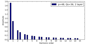
36 Slots, 48 magnets
20mm active length (scalable for "real" hubs, I will built a 40mm version along with the 20mm)
20 turns wind
2x1mm recangular wire with 0,5mm edge radius will give 1,785mm² copper per turn. I got a complete winding stratigie in mind.
1 mm air gap
N35h 6,5 x 3 x 20mm epoxy coating (even got a quote here in Germany: 0,48€ per Piece for N40h. Did it only for interest and they answered very fast...)
1600g for parallel tooth or 1780g for parallel slots active mass
very low flux concept to keep iron losses low. this makes only sense for my special application.

You can have a look @ the attached emetor file. I used the 1A100rpm load point to optimise tooth tip, magnet size and torque ripple. If all electric parameters are fixed, I'm going to make some non-linar runs in emetor for higher loads and a high flux density version for real hub application. In 2 weeks, i will start the CAD construction.

I got some question while playing with the desgin:
- back emf counters torque rippel ... any explanation for that? I have done sims with widening the magnets, the back emf becomes quite sinus like
- any idea to reduce iron loses further?
- does it make sense to give all the edges within the slots a radius for better flux distribution?

Some stupid questions from old "knowlegde":
- RC Outrunners have no lam iron on the rotor, but the have really high rpms, so why?
- still use paper between the lams or coat the lams?

Some questions getting the parts:
- lamination laser cutting: one i got from Miles' Inrunner build tread, any other company to ask?
- do you know anyone here in europe, that can make 2 axis and turing CNC parts from aluminium and steel?
- please advice which FOC controller for this low power application to take, especially for the generator part

F4P
 
Hi F4P,

You're going in the right direction. Perhaps 36t 48p isn't such a great choice for slot/pole combination, though...? It has quite a modest winding factor and also a dominant sub-harmonic which means high magnet losses (ok, you're only running at 400Hz, but...).

You only gain from having a laminated back-iron (performance wise), if you have a problem with eddy currents in the magnets and you have also segmented the magnets.

Hitachi do a 2mm x 1mm magnet wire. Do you have any other source?
 
Miles said:
Hi F4P,

You're going in the right direction. Perhaps 36t 48p isn't such a great choice for slot/pole combination, though...? It has quite a modest winding factor and also a dominant sub-harmonic which means high magnet losses (ok, you're only running at 400Hz, but...).

Which combination would you suggest? I choose the 48 poles to get the 1000rpm at 400Hz. So i can increase the speed later on with a good controller up to 1500rpm or use for the 40mm active lengh version a standard FOC controller like sabvoton at 500rpm with 559 tires.

The slot number comes from the winding schema, i need a continous pattern with 2*N slots per phase. Otherwise it would not work with the thick rectangular wire.

And emetor refuses the simulate setups with a low symetry factors in the free version .

You only gain from having a laminated back-iron (performance wise), if you have a problem with eddy currents in the magnets and you have also segmented the magnets.

Sorry, i do not get it here.

Hitachi do a 2mm x 1mm magnet wire. Do you have any other source?

I'm missing a technical term here? I want to use 2mmx1mm copper wire for the windings.

http://www.scheiing.de/modules/wsShop/article.php?article_id=319897&location_id=72&cat_id=75010

would be the source.
 
You need to check the MMF spectrum in the windings section of Emetor.

This is the chart for 36t 48p....
 

Attachments

  • 36t-48p-spectrum.png
    36t-48p-spectrum.png
    7.4 KB · Views: 2,579
F4P said:
Which combination would you suggest? I choose the 48 poles to get the 1000rpm at 400Hz. So i can increase the speed later on with a good controller up to 1500rpm or use for the 40mm active lengh version a standard FOC controller like sabvoton at 500rpm with 559 tires.

The slot number comes from the winding schema, i need a continous pattern with 2*N slots per phase. Otherwise it would not work with the thick rectangular wire.

36t 44p looks more promising
 
F4P said:
You only gain from having a laminated back-iron (performance wise), if you have a problem with eddy currents in the magnets and you have also segmented the magnets.
Sorry, i do not get it here.
As far as I understand it:

Losses in the magnets and rotor back-iron are principally caused by the sub-harmonics in the airgap MMF.

Segmenting the magnets limits eddy currents.

Losses from eddy currents in the back-iron are reduced by laminating the rotor in conjunction with the segmentation of the magnets. Laminating the rotor without segmenting the magnets can create greater losses.

Magnets can be segmented circumferentially or axially. The greatest gains are from segmenting the shortest side. The use of more than 2 segments circumferentially gives rise to unequal distribution of losses between segments.
 
your motor specs are very close to my v1 Axial Flux motor (I do about 750W mechanical out at 1000 rpm)
my motor weigh more than 2kg but a lot of meat could be cut from it (and certain parts can be made from
plastic instead of alu, mainly the rotor plates holding the magnets in place)

Pictures are here for v1:
http://endless-sphere.com/forums/viewtopic.php?f=30&t=30061&p=434496#p434496

And a triple stator 3hp v2 (complete building instructions):
http://endless-sphere.com/forums/viewtopic.php?f=30&t=46476&p=679460#p679460

And I run it with my homemade FOC controller.

6000 km and counting :D
 
F4P said:
Hitachi do a 2mm x 1mm magnet wire. Do you have any other source?
I'm missing a technical term here? I want to use 2mmx1mm copper wire for the windings.
http://www.scheiing.de/modules/wsShop/article.php?article_id=319897&location_id=72&cat_id=75010
would be the source.
Not really. "Rectangular magnet wire" Magnet wire is enameled copper wire.

Thanks for the link. It's not easy to get the Hitachi wire in small quantities in UK.........
 
Miles said:
As far as I understand it:

Losses in the magnets and rotor back-iron are principally caused by the sub-harmonics in the airgap MMF.

Segmenting the magnets limits eddy currents.

Losses from eddy currents in the back-iron are reduced by laminating the rotor in conjunction with the segmentation of the magnets. Laminating the rotor without segmenting the magnets can create greater losses.

Magnets can be segmented circumferentially or axially. The greatest gains are from segmenting the shortest side. The use of more than 2 segments circumferentially gives rise to unequal distribution of losses between segments.

Thanks for the answer!

So this is what you have done in the 90mm Inrunner? 3 times 10mm magnets in axial direction?
So i should design the motor with lam back iron only with segmented magnets to gain any benefits. Or skip both...
Have you a papier or so to learn on this topic? I want to understand how to find the useful design parameters to choose one option.

I'm currently testing your 44p suggestion. seems to be better...so i will start about thinking how to wire this wired schema.
 
Miles said:
F4P said:
Hitachi do a 2mm x 1mm magnet wire. Do you have any other source?
I'm missing a technical term here? I want to use 2mmx1mm copper wire for the windings.
http://www.scheiing.de/modules/wsShop/article.php?article_id=319897&location_id=72&cat_id=75010
would be the source.
Not really. "Rectangular magnet wire" Magnet wire is enameled copper wire.

Thanks for the link. It's not easy to get the Hitachi wire in small quantities in UK.........

If you need any help to get a quotation write me a PM
 
F4P said:
So this is what you have done in the 90mm Inrunner? 3 times 10mm magnets in axial direction?
So i should design the motor with lam back iron only with segmented magnets to gain any benefits. Or skip both...
Have you a papier or so to learn on this topic?

Yes. 3 axial segments.

As you're doing an outrunner, skip the laminated back-iron. If there's a need to reduce magnet losses, use two magnet segments circumferentially, two or more axially.

See attached thesis.
 

Attachments

  • PhDThesis_EmanueleFornasiero.pdf
    5 MB · Views: 97
Miles said:
As you're doing an outrunner, skip the laminated back-iron. If there's a need to reduce magnet losses, use two magnet segments circumferentially, two or more axially.

See attached thesis.

Is there any chance to do a back iron free sim on emetor?

For building this motor: Isn't easier to glue rectangular magnets in thier a plan cut places at the back iron lamination than buying curved magnet or building a small support structure to glue rectangular magnets to a tube? I haven't built a complete motor from the scratch, only rewund rc motors...

The Thesis only contains useful literature hinds from my horizon of understanding.

From simulating the 36s44p combination i recieve a better sinus like bemf and due to the higher magnet coverage a higher open ciruit voltage, resulting in N19 windings. But i still have no idea how to wind this in real life. What kind of winding simulator did use?

About the Hitachi Magnet Wire cataloge: i can asume that's every where around the world difficult to buy original wire from them without being a company. But i think, the features and the price are complete overkill. And you can buy "normal" rectangular wire as normal guy. 2 times vs. 1 times beding radius doesn't matter and from the heat the magnets will give up earlier than the wires.
 
Lebowski said:
your motor specs are very close to my v1 Axial Flux motor (I do about 750W mechanical out at 1000 rpm)
my motor weigh more than 2kg but a lot of meat could be cut from it (and certain parts can be made from
plastic instead of alu, mainly the rotor plates holding the magnets in place)

Pictures are here for v1:
http://endless-sphere.com/forums/viewtopic.php?f=30&t=30061&p=434496#p434496

And a triple stator 3hp v2 (complete building instructions):
http://endless-sphere.com/forums/viewtopic.php?f=30&t=46476&p=679460#p679460

And I run it with my homemade FOC controller.

6000 km and counting :D

I have read your threads a year ago, absolutly awesome work! Have you ever done any efficiency measurements? for all of the typical loadpoints, i mentioned in the starting post, i want to achieve 94% + bare electric eff. If yes, i will direktly copy it :pancake:

How about your FOC controller at low electric rpms? If you look up for example sinusleistungssteller, eff drops down to 80% something...
 
F4P said:
Is there any chance to do a back iron free sim on emetor?
Unless my memory is playing tricks, there's an option to simulate a Halbach array (Emetor is down at the moment). If that's what you mean?

Or maybe you mean without iron stator core?
 
Miles said:
F4P said:
Is there any chance to do a back iron free sim on emetor?
Unless my memory is playing tricks, there's an option to simulate a Halbach array (Emetor is down at the moment). If that's what you mean?

Or maybe you mean without iron stator core?

Emetor is at least very slow today. I ment a rotor without iron laminations, what you suggested. Halbach is only an option for inrunners as far as my understanding goes, it's something different.

If you use curved magnets for the outrunner and reduce the rotor lam thickness to zero, the flux densitiy spikes and the iron losses went up from 15W to 28W for my desing. I want to have an idea what will happen with my iron losses without iron (should be easy to derive from this sentence :roll: )
 
F4P said:
Lebowski said:
your motor specs are very close to my v1 Axial Flux motor (I do about 750W mechanical out at 1000 rpm)
my motor weigh more than 2kg but a lot of meat could be cut from it (and certain parts can be made from
plastic instead of alu, mainly the rotor plates holding the magnets in place)

Pictures are here for v1:
http://endless-sphere.com/forums/viewtopic.php?f=30&t=30061&p=434496#p434496

And a triple stator 3hp v2 (complete building instructions):
http://endless-sphere.com/forums/viewtopic.php?f=30&t=46476&p=679460#p679460

And I run it with my homemade FOC controller.

6000 km and counting :D

I have read your threads a year ago, absolutly awesome work! Have you ever done any efficiency measurements? for all of the typical loadpoints, i mentioned in the starting post, i want to achieve 94% + bare electric eff. If yes, i will direktly copy it :pancake:

How about your FOC controller at low electric rpms? If you look up for example sinusleistungssteller, eff drops down to 80% something...

No clue, I have no equipment to measure things like this... I kind of go by it takes a lot of power from the battery and
doesn't significantly heat the FETs or motor, so it must be coming out as mechanical power... Plus, it all fits theoretically.
 
Here is another question:

Does anybody know what's the efficiency of a FOC like controller in term of electric rpms and phase current? Or where to get the data?

Which controller should I use? 40A phase current are more than sufficient the the actual design.
 
Is there any reason to have short slot depths? Miles has almost square slots. I get the best results for very deep slot with a ratio depths to width 5:1
 
F4P said:
Is there any reason to have short slot depths? Miles has almost square slots. I get the best results for very deep slot with a ratio depths to width 5:1
Different cases....

For a constant outside diameter:

With an inrunner, you're trading copper area for turning moment and airgap area.

With an outrunner, you're not reducing the airgap diameter when you increase the slot depth............
You can keep on increasing the slot depth on an inrunner until the diminishing amount of copper area gained no longer justifies the additional increase in iron losses.

This is why I maintain that, although you can get a better torque to overall volume ratio with an outrunner, the torque to weight ratio comparison is not so clear cut.....
 
36s48p open ciruit flux distribution.PNG
36s48p

36s42p open ciruit flux distribution.PNG
36s42p

this one of the last question before starting CAD design:
why do i get this heavy flux mismatch? complete same maschine despite magnet poles. it changes only the winding pattern within the stator...

over all i reached all my targets with the 36s48p design so far, but i have the subharmonics still in mind...
 
Back
Top