Congratulations on your successful build! I was quite unprepared for how fast your bike accelerates. I really like the way everything you do, is done with quality, reliability and longevity in mind. Not to mention the sleek looks and wonderfully functional organization and planning of every element; even down to the countersinking of rivets! You are a great inspiration to those who are too tempted to cut corners in order to get the bike build finished (me). Once again well done!!
You are using an out of date browser. It may not display this or other websites correctly.
You should upgrade or use an alternative browser.
You should upgrade or use an alternative browser.
2WD Electric Yuba Mundo Build
- Thread starter teklektik
- Start date
It's great to hear you've found the build interesting, it certainly has provided a lot of enjoyment for me. 
Actually, the bike is a noticeably more frisky than when that video was taken back in early July. Since then I've upped the wattage limit from 3.1kW to 3.3kW and switched from Crystalyte 12 FET Analogs to Lyen 12 FET controllers modified for gear motor use (from Ilia at Ebikes SF). I haven't finished tweaking in the controller programming yet to get the top end squared away, but the bike pulls like a mule into the mid 30s - much stronger than in the configuration in the video. Above that it runs just about like before, maybe a tad slower at the top (gain here, lose there). However, since running flat out at 40+ is not a primary goal, I'm happy to exchange a bit of top end for the much improved low to midrange torque where the actual cruising speed lies.Reactor said:I was quite unprepared for how fast your bike accelerates.
Controller Change: Xlyte -> Lyen
To make a long story short, last July I decided to change from Crystalyte 12 FET Analog controllers to Infineons. Ilia at Ebikes SF is now carrying specially modified Lyen 12 FET controllers (modified by Lyen) for gear motor use. Cell_man Infineons have a good reputation for gear motor use, but I took a flyer on it and went with a couple of the Lyen versions, opting for a mainland supplier. As always, Ilia shipped them out quickly and I got them PDQ.
I did not want to alter the bike wiring harness so this just left the two relatively straightforward tasks:

View attachment 4
Mounting the controllers was a little more interesting since the Lyen controllers are shorter than the Xlytes and the bike mounting arrangement uses aluminum channel with rivnuts - adding new rivnuts ran into other components and wiring that could not be easily moved. Fortunately, the entire Lyen controller from flange to flange fits exactly in between the Xlyte mounting holes. Everything sort of fell together after that discovery - I made up some adapter plates that would clamp the Lyen mounting flanges without actually using the flange mounting holes. This also retained compatibility with the original Xlytes.
View attachment 3
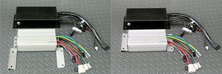
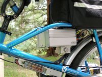
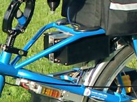
The new controllers are smaller and look pretty good, albeit not quite as stealthy as the black Xlytes. The front mounting brackets wrap over the open space between the two controllers and arguably look better than the original approach. Some black braid on the wiring would have made it a little less conspicuous but it's not too visible under the luggage rack...
EDIT - The rest of the Lyen upgrade tale is here....
To make a long story short, last July I decided to change from Crystalyte 12 FET Analog controllers to Infineons. Ilia at Ebikes SF is now carrying specially modified Lyen 12 FET controllers (modified by Lyen) for gear motor use. Cell_man Infineons have a good reputation for gear motor use, but I took a flyer on it and went with a couple of the Lyen versions, opting for a mainland supplier. As always, Ilia shipped them out quickly and I got them PDQ.
I did not want to alter the bike wiring harness so this just left the two relatively straightforward tasks:
- adapting the connectors to match the existing Xlyte connectors pin-for-pin and
- physically mounting the controllers.
View attachment 4
Mounting the controllers was a little more interesting since the Lyen controllers are shorter than the Xlytes and the bike mounting arrangement uses aluminum channel with rivnuts - adding new rivnuts ran into other components and wiring that could not be easily moved. Fortunately, the entire Lyen controller from flange to flange fits exactly in between the Xlyte mounting holes. Everything sort of fell together after that discovery - I made up some adapter plates that would clamp the Lyen mounting flanges without actually using the flange mounting holes. This also retained compatibility with the original Xlytes.
View attachment 3


The new controllers are smaller and look pretty good, albeit not quite as stealthy as the black Xlytes. The front mounting brackets wrap over the open space between the two controllers and arguably look better than the original approach. Some black braid on the wiring would have made it a little less conspicuous but it's not too visible under the luggage rack...
EDIT - The rest of the Lyen upgrade tale is here....
thickhead
100 mW
Re: Lyen controllers... what does "modified for gear motor use" actually mean? I have one of these from Ilia on my cargo bike (with a BMC V2T).
In broad terms: stock Infineon controllers seem to judder and lurch into motion when used with MACs and BMCs - a far cry from the smooth getaways achieved with old school Crystalyte Analog controllers. However, cell_man has been successful in achieving smooth getaways by modding the hardware and using a couple of twists on the firmware programming. His controllers are arguably The Standard for MAC use. Lyen has recently followed with (presumably similar) mods to his line of Infineon controllers.thickhead said:Re: Lyen controllers... what does "modified for gear motor use" actually mean? I have one of these from Ilia on my cargo bike (with a BMC V2T).
It would be interesting to run controllers from these two vendors side-by-side, especially considering the maturity of cell_man's efforts. (Needs another post about how the Lyen stuff is working out...
thickhead
100 mW
teklektik said:In broad terms: stock Infineon controllers seem to judder and lurch into motion when used with MACs and BMCs - a far cry from the smooth getaways achieved with old school Crystalyte Analog controllers...
Ah! Very interesting. I still am at the bottom end of my learning curve regarding controllers (I get the basics of PWM, but don't know squat about how the devices are actually built). On my BMC+Lyen powered bike there is a pleasing low growl as the bike starts up, so I would consider it "smooth". However, since this is my first controller on my first build, I don't have a standard of comparison. Motivated by your comment, sounds like I might enjoy picking up another controller to play with and compare.
I haven't spent too much time looking around for detailed circuit descriptions--any pointers to info on how these hardware and firmware mods are done? Or is it a occult practice known only to third degree ninja EEs?
There is an ocean of information about these controllers on ES - which in a way is the problem - there is no single succinct repository and there are several versions of the controllers. Best to rummage about based on your particular need...thickhead said:I haven't spent too much time looking around for detailed circuit descriptions--any pointers to info on how these hardware and firmware mods are done? Or is it a occult practice known only to third degree ninja EEs? How much of the firmware tuning is accessible from the programming interface?
- There are some tips on searching in this post: Do people even try reading or searching anymore?
- The basics for the Keywin Infineon firmware downloader can be found here.
- Info about XPD, a replacement for the original Keywin downloader, is located here (haven't tried it - I use the Lyen MK2 downloader).
Since the MAC and BMC are virtually identical and the cell_man and Lyen controller mods appear to be similar, it's not unreasonable to pursue cell_man controller/MAC programming information with your Lyen/BMC - at least in principle.thickhead said:Re: Lyen controllers... I have one of these from Ilia on my cargo bike (with a BMC V2T).
If you want to reprogram your controller, I would recommend getting started by obtaining a programming cable from Ilia along with a copy of Lyen's MK2 downloader application (distributed to Lyen customers). Or go directly to Lyen. I would highly recommend getting a CA V3 before you begin jacking up the power to your BMC - it will pay for itself in the first clutch replacement you don't need to make...
thickhead
100 mW
Thanks very much, telektik, for the detailed reply and suggestions. I know how to pretty effectively search ES (using google or similar), and already have a bunch of controller setup threads bookmarked. But as you say, there's not really a single canonical source for this info. It may not be apparent to you, but most of the threads I've read on controller modding still seem to assume background knowledge of practical power electronics that I do not possess (yet). I'm going to start with the tuning procedure described by mwkeefer. I bought a programming cable from Ilia when I purchased the motor (despite his trying to warn me about doing so), and downloaded the Lyen application shortly thereafter. This fall I'm just getting some miles logged on the "stock" setup before start tweaking anything. I would at least want a temp sensor (if not a CA V3) before I tried to push too many watts through the BMC.
What I was asking about was the particular gear-motor-friendly mods you were alluding to, and you confirmed my expectation that these would be treated as semi-proprietary by cell_man and Lyen.
Sorry to derail your beautiful thread on your amazing build. It really is an inspiration.
What I was asking about was the particular gear-motor-friendly mods you were alluding to, and you confirmed my expectation that these would be treated as semi-proprietary by cell_man and Lyen.
Sorry to derail your beautiful thread on your amazing build. It really is an inspiration.
That particular post is interesting, however, there are other valuable posts in that thread as well - I encourage you to plow through it. I found mwkeefer's stuff to be very informative.thickhead said:I'm going to start with the tuning procedure described by mwkeefer.
I would like that as well, but Ilia has emphasized the difficulty in pulling new BMC wiring. I would be interested in your experiences in that area.thickhead said:I would at least want a temp sensor (if not a CA V3) before I tried to push too many watts through the BMC.
Yes, and it is a bit challenging to discuss modifications and 'discovered' facts while still honoring this loosely proprietary information since there are clear financial consequences for these guys. I will get a post together shortly that I hope will be useful...thickhead said:What I was asking about was the particular gear-motor-friendly mods you were alluding to, and you confirmed my expectation that these would be treated as semi-proprietary by cell_man and Lyen.
thickhead
100 mW
Well... that's confusing. I thought the CA V3 required a temp sensor installation, anyway, since it just displays the sensor's output (and can use it as a temperature-controlled throttle limiter). In any case, yes, I will keep everyone informed of my (mis)adventures in this area!teklektik said:I would like that as well, but Ilia has emphasized the difficulty in pulling new BMC wiring. I would be interested in your experiences in that area.thickhead said:I would at least want a temp sensor (if not a CA V3) before I tried to push too many watts through the BMC.
All the sensors (including throttle) are optional or can be disabled. Please see the first configuration item in section 10 of the CA V3B19 Setup.thickhead said:Well... that's confusing. I thought the CA V3 required a temp sensor installation
It's unfortunate that the BMCs cannot be obtained with a pre-installed temp sensor, but BMC has a reputation of being uncooperative with its retailers. This actually led to a bit of a retailer exodus a year or so ago, and now even Ilia is switching over to MACs...
thickhead
100 mW
Yes... I meant "required if you want temperature measurements". If you don't disable them, then one has to have a motor with a temp sensor installed. The CA V3 does not solve this problem for the end user. Point being: CA V3 just makes it easier to use the temp data, but it doesn't actually provide an easier sensor solution. So, since one has have a sensor installed in any case, the CA V3 is only nice to have, but a voltmeter or some other device would be just about as easy to use (if one already has CA V2.X instead), assuming you just want to monitor the temperature.teklektik said:All the sensors (including throttle) are optional or can be disabled.thickhead said:Well... that's confusing. I thought the CA V3 required a temp sensor installation
I agree--it is a pity. I recall an interview with Justin in which he discussed this issue: the western hobbiest/hacker market is a drop in the ocean for the Chinese manufacturers, and so it's difficult to get them to make modifications that are not being demanded by their own market. Other than the nominally better water resistance of the BMC casing as compared to the MAC (less seams, according to Ilia), with the new MAC gearing there seems to be little difference between the too. I'm planning on a MAC (or two?) for my next build. I believe cell_man is selling them with temp sensors pre-installed (link right after a post of yours!).It's unfortunate that the BMCs cannot be obtained with a pre-installed temp sensor, but BMC has a reputation of being uncooperative with its retailers. This actually led to a bit of a retailer exodus a year or so ago, and now even Ilia is switching over to MACs...
I must disagree - V3 throttle ramping is a huge feature for high powered gear motors and unavailable on V2.x. This is really a game changer - I've run both a V2.3 and a V3 on the bike and could never go back...thickhead said:...the CA V3 is only nice to have, but a voltmeter or some other device would be just about as easy to use (if one already has CA V2.X instead).
Although this may essentially be true at normal power levels, for tweaked installations I must disagree. Both vendors have made such noteworthy strides in improving the gears that the clutch may now be the focus as the weak link in the chain (IMHO). Although the BMC also has true oil (water) seals on the shaft and uses quality NSK bearings, the real difference lies in the V4 clutch. The BMC pre-V4 and MAC clutches are essentially identical, but the V4 clutch is of different construction and seems extremely rugged. My V3 or MAC clutches have all gotten smoked but the V4 clutches just keep on working in spite of prolonged customer abuse. For me, they are worth the high price compared to MAC clutches. Being able to ride with little concern for safeguarding the motor innards is part of what gives the bike a 'production quality' instead of DIY feel... (Lately I've been thinking of a MAC upgraded with a V4 clutch...thickhead said:Other than the nominally better water resistance of the BMC casing as compared to the MAC (less seams, according to Ilia), with the new MAC gearing there seems to be little difference between the two.
So, I broke down on Monday and bought a GoPro HD2 and it just arrived - barely in time for Fall foliage!
Yahoo!
Tried it real quick - all's well - went on-line to check details of RageCam lenses, and....
You have got to be kidding me....
GoPro announced the HD3 on Tuesday...
Yahoo!
Tried it real quick - all's well - went on-line to check details of RageCam lenses, and....
You have got to be kidding me....
GoPro announced the HD3 on Tuesday...
Beachcruzer
100 W
teklektik said:So, I broke down on Monday and bought a GoPro HD2 and it just arrived - barely in time for Fall foliage!
Yahoo!
Tried it real quick - all's well - went on-line to check details of RageCam lenses, and....
You have got to be kidding me....
GoPro announced the HD3 on Tuesday...
. . .and on Wednesday they announced the GoPro HD3 . . .
GoPro® Launches New HD HERO3 Camera Line Featuring Smallest 4K Camera
Smaller, Lighter, More Powerful with Built-in Wi-Fi Camera Available in Three Editions
SAN MATEO, CA (October 17, 2012) - GoPro, maker of the world's most versatile and durable cameras and producer of today's most engaging content announces the release of its new HD HERO3 camera line up in White, Silver and Black editions. Each new edition retains the iconic look of the previous award winning HD HERO cameras but comes in at about half the size of its predecessors and has built-in Wi-Fi technology. At the top end of the new product line up, the HD HERO3 Black Edition is one of the most powerful camera systems available, delivering astounding 4K and 2.7K video resolutions all in the size of a small box of matches, making it easier to share your world. The White, Silver and Black editions are available for pre-order at GoPro.com and are shipping to specialty retailers around the world for MSRP $199.99, $299.99 and $399.99 respectively.
Check it all out here - http://www.gopro.com/
Battery Update
Some pages back I mentioned that after testing different battery configurations, I decided to go with 20s2p for the final pack. After an entire season of 'other stuff', I still haven't fabbed new battery enclosures, so here's the battery part of the tale separate from the enclosure project…
Increased Voltage + CA = Increased Range
The spreadsheet below calculates battery capacity (Wh) and estimates range - fill in values in the pink cells at the top and the table will populate appropriately. (If you do not have Excel, download and install free Apache Open Office.) The image below is a snap of that spread with values for Headway 38120 cells.
View attachment 1
View attachment seriesCellCalculator_4.xls
Since Wh = V x Ah, increased capacity comes with increasing voltage or Amp hours. This leads to the somewhat non-intuitive idea of increasing range by increasing voltage. Conventionally this is considered the strategy for increasing speed, however, we can make this work by limiting the controller current to restrict the available motor power. With power consumption unchanged, increased Wh yields greater range. Since the bike was already using the CA to limit current for one/two motor operation, this higher pack voltage approach actually required no changes.
The yellow spreadsheet cells highlight 'interesting' configurations for this build. In my case, the weight of 16s2p was acceptable but the resulting range was not; on the other hand, the conventional range-increasing move to 16s3p increased battery size and weight by 50% - big and heavy. From a purely Wh perspective, the intermediate choice of 20s2p was 'just right'. At about 25 Wh/mi (my average as measured by CA) the spreadsheet shows an estimated range increase from 32 mi (16s2p) to 41 mi (20s2p) which fulfilled my needs.
There were three voltage-related considerations which appeared to provide no obstacles:
Power Management: CA V3
The 20s2p pack and CA V2 limiting successfully yielded the estimated range but two problems became immediately evident:
 .
.
Boosting the voltage with 20s2p has also made it possible to use the V3 power throttle configuration so the bike runs pretty much the same at the beginning and end of the ride, in hot weather or cold. The CA automagically deals with lower pack voltages by kicking up the controller amps so the delivered motor power is unchanged.
I have over 2500 miles on the 20s2p battery configuration and about 1500 miles on the V3 with the relevant firmware features in place. No issues and working very nicely…
Some pages back I mentioned that after testing different battery configurations, I decided to go with 20s2p for the final pack. After an entire season of 'other stuff', I still haven't fabbed new battery enclosures, so here's the battery part of the tale separate from the enclosure project…
Increased Voltage + CA = Increased Range
The spreadsheet below calculates battery capacity (Wh) and estimates range - fill in values in the pink cells at the top and the table will populate appropriately. (If you do not have Excel, download and install free Apache Open Office.) The image below is a snap of that spread with values for Headway 38120 cells.
View attachment 1
View attachment seriesCellCalculator_4.xls
Since Wh = V x Ah, increased capacity comes with increasing voltage or Amp hours. This leads to the somewhat non-intuitive idea of increasing range by increasing voltage. Conventionally this is considered the strategy for increasing speed, however, we can make this work by limiting the controller current to restrict the available motor power. With power consumption unchanged, increased Wh yields greater range. Since the bike was already using the CA to limit current for one/two motor operation, this higher pack voltage approach actually required no changes.
The yellow spreadsheet cells highlight 'interesting' configurations for this build. In my case, the weight of 16s2p was acceptable but the resulting range was not; on the other hand, the conventional range-increasing move to 16s3p increased battery size and weight by 50% - big and heavy. From a purely Wh perspective, the intermediate choice of 20s2p was 'just right'. At about 25 Wh/mi (my average as measured by CA) the spreadsheet shows an estimated range increase from 32 mi (16s2p) to 41 mi (20s2p) which fulfilled my needs.
There were three voltage-related considerations which appeared to provide no obstacles:
- The recommended BMC voltage max is 60v but the nominal 20s pack voltage is 66v. This wasn't too far afield and since 60v was just a guideline - close enough.
- The DC/DC converter has an input voltage limit of 72v. The 20s hot-off-the-charger voltage is 73v - close enough.
- The system relay to switch Vbatt by the keyswitch has a 48v coil. The coil resistance is 1.5K giving it a power dissipation of about 1.2W. Overvolting it to 73v increases the power proportionately to about 150% or 1.8W - acceptable for open air situations where heat buildup would not be an issue.
Power Management: CA V3
The 20s2p pack and CA V2 limiting successfully yielded the estimated range but two problems became immediately evident:
- The high voltage gave the controller/motor combination a fairly radical step in power midway in the throttle range of motion. Using simple current limiting with a CA V2.23 made speeds in the steep part of the throttle curve difficult to maintain - paying continuous attention to tweaking the throttle took a bit of the fun out of the ride.
- More importantly, the CA V2 limiting does not scale the throttle, but rather introduces a ceiling to the existing throttle curve. This means that until the ceiling is reached and limiting kicks in, the controllers/motors behave as if the CA was not even connected; this type of limiting does nothing to diminish gear/clutch stress on getaways. Sadly, this resulted in more than a couple of seized clutches for me. The slightly high 66v pack voltage was not as harmless as assumed. (Well, okay, there was operator abuse afoot as well... :wink: )
Boosting the voltage with 20s2p has also made it possible to use the V3 power throttle configuration so the bike runs pretty much the same at the beginning and end of the ride, in hot weather or cold. The CA automagically deals with lower pack voltages by kicking up the controller amps so the delivered motor power is unchanged.
I have over 2500 miles on the 20s2p battery configuration and about 1500 miles on the V3 with the relevant firmware features in place. No issues and working very nicely…
This is a bit of a long post, but the CA V3 and Lyen controller configurations go hand-in-hand so here's details on both…
Lyen Controller Upgrade
A few posts back I described mounting Lyen EB312 controllers (modified by Lyen for gear motor use) in place of my original Crystalyte Analog 12 FET controllers. Unfortunately, when I ran the new controllers I found that each of the three (two on the bike and a spare) performed differently, presumably because of parts tolerances and differences in soldering the shunts. These differences were Not Good since the bike design is predicated on the idea of two identical controllers/motors/wheels that equally share the power allocation from a single CA. So - I somewhat unhappily had to learn to do some controller programming to equalize performance. But in the end, this provided an opportunity to make the controllers and CA V3 work together pretty nicely.
CA V3 & Controller Closed Loop Operation
By the time the controller swap was underway, I was running a CA V3 with closed loop current throttle to help address the tweaky throttle mentioned in the previous post; this was upgraded to power throttle when the feature became available. An explanation of how the CA closed loop control works and can refine throttle control may be found in this post. Below is a diagram of the CA V3 and controller interaction for this build. This is basically the same as the single controller situation but both controller/motor pairs act on the same load and so affect each other by changing the apparent load seen by the other.
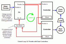
Configuration Overview
The strategy is to configure the V3 and controllers to give a throttle/power curve that cannot be achieved with either individually and that is optimized for BMC/MAC. Nothing magical here, but the midrange config is slightly interesting. The configuration can be viewed in three power zones:
Performance
Skipping ahead to the result before plodding through the configuration details we see the present (2WD/1WD switch) and (LHM switch) power matrix looks like this:
View attachment 4
Notice in each plot how the throttle (orange line) goes to WOT on startup and stays there but the CA ThrottleOut to the controllers (green line) drops to limit the power (blue line).
View attachment 3
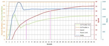
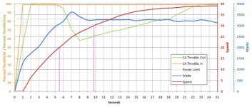
The plots show smooth and well-behaved speed curves (red lines) with no sudden changes in slope. The low end power is clearly restrained by the CA throttle ramping. The noticeable rise in the speed curve at the low-midrange is the effect of the high current configuration of the controllers - in this range they operate like dual 2200W units; at those speeds they are not drawing 4400W, but the bike experiences the strong midrange power curve of controllers of that power rating. Towards the top end, CA 3300W limiting takes over, holding peak motor power consumption down as the speed curve flattens out to a top speed of about 40mph. Under load on hills, the CA top end limiting just takes over sooner at a lower speed.
Configuration Details
Here are the relevant configuration parameters for the CA v3 (B19 firmware):
Rated/Phase Current Config
There are some small rated/phase current differences between the front and rear controllers to obtain equivalent power/performance in spite of minor controller hardware differences, however, both use the same low phase-to-rated current ratio of about 2:1. Increasing the rated current while lowering the current ratio pushes the power curve upward making the low end smoother and the higher speeds more powerful. Without limiting, the individual controller configurations would run about 2200W each - too extreme for BMC motors. However, the high current configuration is moderated at dead start and the top end by the CA as mentioned above.
The current values shown are the effective controller values, not the values entered into the Lyen programming software. There are two strategies to address programming cell_man/Lyen modified controllers:
Block Time/Speed/LVC Config
The controller block time is as short as possible (0.1 sec) - essentially disabled.
LVC detection is localized with the CA and the controller LVC values are set as low as possible.
I did not finish experiments with different Speed% settings and am presently running at 115%. I tried this because the Crystalyte controllers seemed somehow smoother at the top end. Since Speed% settings over 100% are reported to reduce phase current at the top end, it seemed worth a try as a means to 'loosen up' the motor at speed. However, my attention got redirected to other issues and I just left the controllers with the 115% configuration without finishing testing - all seems to be working fine but I cannot offer any assessment of the relative effectiveness of the setting - 100% might be just as good… (yet another thing to do next Spring).
Other threads about 2WD mention problems with motor 'contention' which is characterized by a kind of ratty power application at lower power levels when PWM is in play. Experiencing this behavior was a little surprising since the phenomenon never occurred with the Crystalyte Analog controllers which ran together smooth as silk. In any case, I detected two types of 'contention' with the Lyen controllers: (1) between the CA and the controllers and (2) between the two controllers.

Summary
The Lyen controller and CA V3 upgrade have worked out great and give the bike a nice production feel with very satisfying power and easy throttle control. It's extremely smooth off the line and requires no special care to avoid wheel spin or to protect gears/clutches. The bike tops out at just under 40mph, does 0 to 30 in under 10 seconds (150lb bike + 200lb rider), and zips up hills. The result is a really nice improvement over the original Crystalyte Analogs and CA V2. These changes took more effort than I had foreseen, but I am a very happy camper
Lyen Controller Upgrade
A few posts back I described mounting Lyen EB312 controllers (modified by Lyen for gear motor use) in place of my original Crystalyte Analog 12 FET controllers. Unfortunately, when I ran the new controllers I found that each of the three (two on the bike and a spare) performed differently, presumably because of parts tolerances and differences in soldering the shunts. These differences were Not Good since the bike design is predicated on the idea of two identical controllers/motors/wheels that equally share the power allocation from a single CA. So - I somewhat unhappily had to learn to do some controller programming to equalize performance. But in the end, this provided an opportunity to make the controllers and CA V3 work together pretty nicely.
CA V3 & Controller Closed Loop Operation
By the time the controller swap was underway, I was running a CA V3 with closed loop current throttle to help address the tweaky throttle mentioned in the previous post; this was upgraded to power throttle when the feature became available. An explanation of how the CA closed loop control works and can refine throttle control may be found in this post. Below is a diagram of the CA V3 and controller interaction for this build. This is basically the same as the single controller situation but both controller/motor pairs act on the same load and so affect each other by changing the apparent load seen by the other.

Configuration Overview
The strategy is to configure the V3 and controllers to give a throttle/power curve that cannot be achieved with either individually and that is optimized for BMC/MAC. Nothing magical here, but the midrange config is slightly interesting. The configuration can be viewed in three power zones:
- Startup - Low End: Minimize gear/clutch stress by disabling the Infineon controller Block Time feature to eliminate the 'kick in the pants' unlimited current off the line. Replace this high current boost with the exact opposite - smooth application of reduced current using the V3 throttle ramping feature
- Low-Midrange: Once rolling, use an aggressive high power controller configuration to get high available midrange torque. The high torque can be applied with controlled midrange acceleration over a longer time period to offset the loss of the initial Block Time boost.
- High End: Use the CA V3 power or current limiting to limit maximum motor power to safe levels. This allows the controllers to be configured for an excessively high rated current to yield an abnormally aggressive midrange power curve. This V3 maximum power level is set to improve travel range (see preceding battery post) and to avoid pushing the motors into an inefficient high rpm region where there is excessive motor heat generation.
Performance
Skipping ahead to the result before plodding through the configuration details
View attachment 4
- Caveat: With both motors engaged each sees one half the load from net vehicle weight, hills, and wind. Two motor operation substantially reduces motor stress and heating making 1-motor/High the most taxing setting (red cell in chart above). This mode is used only in case of a motor/controller failure (limp home mode).
Notice in each plot how the throttle (orange line) goes to WOT on startup and stays there but the CA ThrottleOut to the controllers (green line) drops to limit the power (blue line).
View attachment 3


The plots show smooth and well-behaved speed curves (red lines) with no sudden changes in slope. The low end power is clearly restrained by the CA throttle ramping. The noticeable rise in the speed curve at the low-midrange is the effect of the high current configuration of the controllers - in this range they operate like dual 2200W units; at those speeds they are not drawing 4400W, but the bike experiences the strong midrange power curve of controllers of that power rating. Towards the top end, CA 3300W limiting takes over, holding peak motor power consumption down as the speed curve flattens out to a top speed of about 40mph. Under load on hills, the CA top end limiting just takes over sooner at a lower speed.
With a 26" rim and Fat Franks (2150mm) these recommendations work out to be:cell_man said:The other thing to consider is that there is a limit to the rpm these motors will efficiently operate to. There are 80 electrical cycles per revolution with the 16 pole motor and 5:1 gear reduction. If you run the motor much above 400rpm the motor will get hotter due to inefficiencies in the stator that are unavoidable. I would say that the max rpm you should operate is maybe around 500rpm which equals about 60kph in a 26" rim, but closer to 50kph is advisable. If you are really obsessed with having big power, fit dual motors, it really flies and the motors will not be stressed doing it, but the motors will still be limited by the max rpm of the motor.
-
Code:
  rpm-limited speed: (500rev/min) x (2150mm/rev) / (1609344 mm/mi) x (60 min/hr) = 40.7 mi/hr
max efficient speed: (400rev/min) x (2150mm/rev) / (1609344 mm/mi) x (60 min/hr) = 32 mi/hr
preferred top speed: (50kph/60kph) = 83.33% of max speed
                     40.7mi/hr x (83.33/100) = 33.9mph
Configuration Details
Here are the relevant configuration parameters for the CA v3 (B19 firmware):
-
Code:
Plim -> Max Current = [75.0] Amps
Plim -> AGain = [110] Gain
Plim -> Max Power = [3300] Watts
Plim -> W Gain = [10] Gain
ThrI -> Cntrl Mode = { Power (W) }
ThrO -> Up Ramp = [32]
ThrO -> Down Ramp = [400]
Ctrl -> Aux Funct = { Power Lim }
Rated/Phase Current Config
There are some small rated/phase current differences between the front and rear controllers to obtain equivalent power/performance in spite of minor controller hardware differences, however, both use the same low phase-to-rated current ratio of about 2:1. Increasing the rated current while lowering the current ratio pushes the power curve upward making the low end smoother and the higher speeds more powerful. Without limiting, the individual controller configurations would run about 2200W each - too extreme for BMC motors. However, the high current configuration is moderated at dead start and the top end by the CA as mentioned above.
The current values shown are the effective controller values, not the values entered into the Lyen programming software. There are two strategies to address programming cell_man/Lyen modified controllers:
- cell_man: program the controller using the true board type (e.g. EB312) and mathematically manipulate the desired values into the configuration parameter values
cell_man said:o00scorpion00o said:... you have to set the amps to (HALF) what you need... - Lyen: program the controller using a more powerful board type (e.g. EB318 instead of EB312) and program using the actual parameter values. (See this related thread on the topic of running a non-hub BMC gear motor with a Lyen controller.)
Block Time/Speed/LVC Config
The controller block time is as short as possible (0.1 sec) - essentially disabled.
LVC detection is localized with the CA and the controller LVC values are set as low as possible.
I did not finish experiments with different Speed% settings and am presently running at 115%. I tried this because the Crystalyte controllers seemed somehow smoother at the top end. Since Speed% settings over 100% are reported to reduce phase current at the top end, it seemed worth a try as a means to 'loosen up' the motor at speed. However, my attention got redirected to other issues and I just left the controllers with the 115% configuration without finishing testing - all seems to be working fine but I cannot offer any assessment of the relative effectiveness of the setting - 100% might be just as good… (yet another thing to do next Spring).
- Caveat: Although this general V3/controller config scheme will work nicely for single gear motor builds, the settings above heavily tax the clutches in this 2WD setup (remember: only half the load each). BMC V4 clutches are a new rugged design and are holding up well, but the earlier design MAC and pre-V4 BMC clutches have seized. Although this has a great deal to do with riding style (aka 'customer abuse'), please do not consider these exact settings to be 'safe'
Other threads about 2WD mention problems with motor 'contention' which is characterized by a kind of ratty power application at lower power levels when PWM is in play. Experiencing this behavior was a little surprising since the phenomenon never occurred with the Crystalyte Analog controllers which ran together smooth as silk. In any case, I detected two types of 'contention' with the Lyen controllers: (1) between the CA and the controllers and (2) between the two controllers.
- The CA interaction was not very pronounced but the effects were all but eliminated by decreasing the CA ThrO->DownRamp setting from the original [999] to [400] - the ThrO->UpRamp setting was already set very low to [032]. Together these effectively damped the CA ThrottleOut response while leaving the controllers with a fairly rapid response. The differing time constants appear to prevent the CA and controllers from getting into the over-correction lockstep of 'contention'.
- The controller/controller 'contention' was apparent when the controllers had identical default Lyen-style configurations. The interaction between the two controllers essentially disappeared when I switched to the cell_man controller programming technique and finalized the configuration as shown above with higher power, the 2:1 current ratio, and slightly dissimilar controller current settings. I was not actually attempting to address the 'contention' issue but something accidentally remedied the matter. Whatever the cause - a somewhat puzzling but welcome resolution…
Summary
The Lyen controller and CA V3 upgrade have worked out great and give the bike a nice production feel with very satisfying power and easy throttle control. It's extremely smooth off the line and requires no special care to avoid wheel spin or to protect gears/clutches. The bike tops out at just under 40mph, does 0 to 30 in under 10 seconds (150lb bike + 200lb rider), and zips up hills. The result is a really nice improvement over the original Crystalyte Analogs and CA V2. These changes took more effort than I had foreseen, but I am a very happy camper
ohzee
100 kW
So stripped down my yuba tonight. going to take it to the LBS tomorrow to have it adjusted some.
Anyway wanted to copy how you routed your cabling thru the tube.. Just looked over your pictures to
see where you put your holes and man this is one of the most detailed build logs I have seen.
Your pretty bad a$$ great work and thanks again for all the reference material going to steal some more
of your ideas.
ohzee-
Thanks - it's satisfying to hear some of the thread is finding a home in another bike - looking forward to seeing how your own build comes out!
On pulling the wires: your experience may vary, but I was unsuccessful at pulling wires because of the tight squeeze to left/right of the seat tube where it passes through the top tube. Instead, I pushed the wires past from the butt end of the top tube and hooked them with a curved dental pick (a bent big paperclip would work) as they slid past the elongated hole near the head tube. Once I had this worked out, it went without too much cursing. I pulled the wiring without connectors and just left a few feet of extra wire at each end of the top tube, then routed and connectorized in situ.
On the other hand, I'm thinking you won't have front phase wires to take up a lot of space so there might not be so much self-inflicted suffering... :wink:
ohzee
100 kW
Yea exactly - running my 5404 in the rear it seems to do plenty for me. Only part that sucks is the lack of gears.
Can I ask what you used to cover the holes you cut ? Where the metal would be sharp. figured you came up with something
that worked pretty good so as to not wear down the wires. I thought about using some liquid tape , but thought id ask.
going to go pick up my bike now - I will finally have a nice set of brakes on this thing. I am going to need it with this
24fet monster.. plan on doing 24s life with 90 amps. Gonna setup some turn signals brake lights running lights etc..
as well.. Ill make sure to get a pic up when I am done.
I don't think liquid tape will be up to the task and takes forever to dry hard, but this is brand-dependent, so you may have fair luck with it.ohzee said:Can I ask what you used to cover the holes you cut ? Where the metal would be sharp. figured you came up with something
that worked pretty good so as to not wear down the wires. I thought about using some liquid tape...
I started by grinding the edges smooth inside and with my trusty Dremel. To protect the wiring, I got a grommet with a large ID but small cross section from a local electronics store. (I believe it was a 1-1/8" OD 13/16" ID 3/64" groove, pn GRM-1105P). I sliced it then fit it around the ID of the hole and finally sliced off the extra, leaving it a tiny bit too long so it would compress into the opening nicely. Worked great but I underestimated the diameter of the wire bundle and the holes were already large, so I sadly eliminated the grommet altogether.
If you are in a hurry and don't have a local source for a big donor grommet, you can try using some very small diameter tubing and just slit it up the side. You might try gas model fuel line at a hobby store or perhaps aquarium air line from a local pet store.
Anyhow, I switched to using epoxy that I tinted matching blue with a bit of blue and white resin color pigment (old marine supply goodies). I just dabbed it around the opening and built up a little bulging lip, making sure to get it onto the interior surface of the tubes a bit as well. It flowed into a nice smooth rounded edge. You can do this easily with 5 or 30 minute epoxy - just tint up the slightly colored A or B part to get a color match so you can take your time. Then add in the other (clear) component to get things cooking. The pigments generally come in little jars or squeezy tubes - (Google 'resin pigment') - try stopping by a local boating store or chandlery. Of course, you can just forego the tint altogether - there's really not much epoxy visible anyway - I just used stuff at hand...
BTW - Isopropyl alcohol is a solvent for epoxy and you can use it to clean up accidents and fingers until it sets up.
ohzee
100 kW
thanks tek - gave me some great ideas.. off I go to see what I can find.
ohzee-
BTW - If you are going to use the tubing approach, a pretty good way to slit it is to tape the tubing into a V-shaped jig - the corner of the fence and saw table or a piece of wood or thick wooden ruler taped to a countertop. With the tubing fully taped down in the V without twists, etc, you can use a straightedge as a guide and cut on a radius of the tubing center with an Xacto or sharp utility knife. You will only need a few inches of nice straight cut, so even if the tubing squirms a bit, you should be able to salvage a couple of good sections...
BTW - If you are going to use the tubing approach, a pretty good way to slit it is to tape the tubing into a V-shaped jig - the corner of the fence and saw table or a piece of wood or thick wooden ruler taped to a countertop. With the tubing fully taped down in the V without twists, etc, you can use a straightedge as a guide and cut on a radius of the tubing center with an Xacto or sharp utility knife. You will only need a few inches of nice straight cut, so even if the tubing squirms a bit, you should be able to salvage a couple of good sections...
Frame Lock as Front Wheel Lock
For some time I've been wanting a Dutch style frame lock so I can just run into a store quick-like - just a really convenient medium security lock. Since the bike weighs about 150lb and is over 6ft long, it's not the kind of thing that someone will easily carry away - a no-chain wheel lock is adequate for casual use. The nice thing about frame locks is that they are really wheel locks so the deterrent is that the bike can't be ridden with something locked around the tire - the actual mount for the lock itself need not be particularly secure.
Unfortunately, I chose to install all the electronics on the seat stays exactly where frame locks mount. I looked at other mounting points in the rear but they were all just too tough to easily access (under panniers, etc). Thinking about it a bit, I decided to mount a lock on the front wheel where it would also serve as a visual deterrent. I opted for an ABUS Amparo 4850 SP/LH which has a key that can be removed when unlocked. I got it from Lockitt.com - good price and fast delivery.
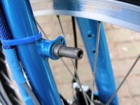
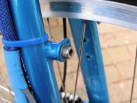
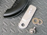
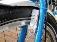
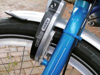
I also bought a mounting ear kit designed for rear mounting on the v-brake studs but it didn't work out for the front. Since I have a front disc brake, I chose to mod the front v-brake studs and fab a couple of tabs to mount the lock. I cut down the studs leaving a short 10mm boss using a Dremel cutoff wheel. The aluminum tabs are made from 1/8x1" bar stock and are bored with a 10mm hole and held in place with a 6mm socket head screw and fender washer. The lock is mounted to the tabs with 5mm screws and nylocks. The lock has little removable plastic covers that hide the mounting screws. The only minor bump in the road is the need for a spacer so the lock will clear the bolt head that holds the tabs to the v-brake studs - this is made from a bit of extra 1/8x1" aluminum bar stock. The spacer plate is epoxied to the tab and both were drilled/tapped together so the 5mm screws would appear as fixed mounting studs. The heat from shaping the tabs later separated the epoxy but the holes were already aligned and tapped, so no problem...
View attachment 1
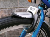
The assembly is very rigid and the lock ended up fairly close to the head tube so it doesn't look too much like an after-thought. On the other hand, with the lights, camera mount, disk brake, hub motor, and now a lock - it's a busy little front end...
The lock is set by inserting and turning the key, then pushing down the protruding ear on the right side. This slides the curved hasp between the spokes and into the other side of the lock. Inserting and turning the key releases the hasp and a spring snaps it up out of sight into the right side of the lock.
The lock is a hit . It's always ready and is super easy to use. Although not suitable for high security applications, it has its place and fills one of my common locking needs very nicely.
For some time I've been wanting a Dutch style frame lock so I can just run into a store quick-like - just a really convenient medium security lock. Since the bike weighs about 150lb and is over 6ft long, it's not the kind of thing that someone will easily carry away - a no-chain wheel lock is adequate for casual use. The nice thing about frame locks is that they are really wheel locks so the deterrent is that the bike can't be ridden with something locked around the tire - the actual mount for the lock itself need not be particularly secure.
Unfortunately, I chose to install all the electronics on the seat stays exactly where frame locks mount. I looked at other mounting points in the rear but they were all just too tough to easily access (under panniers, etc). Thinking about it a bit, I decided to mount a lock on the front wheel where it would also serve as a visual deterrent. I opted for an ABUS Amparo 4850 SP/LH which has a key that can be removed when unlocked. I got it from Lockitt.com - good price and fast delivery.
I also bought a mounting ear kit designed for rear mounting on the v-brake studs but it didn't work out for the front. Since I have a front disc brake, I chose to mod the front v-brake studs and fab a couple of tabs to mount the lock. I cut down the studs leaving a short 10mm boss using a Dremel cutoff wheel. The aluminum tabs are made from 1/8x1" bar stock and are bored with a 10mm hole and held in place with a 6mm socket head screw and fender washer. The lock is mounted to the tabs with 5mm screws and nylocks. The lock has little removable plastic covers that hide the mounting screws. The only minor bump in the road is the need for a spacer so the lock will clear the bolt head that holds the tabs to the v-brake studs - this is made from a bit of extra 1/8x1" aluminum bar stock. The spacer plate is epoxied to the tab and both were drilled/tapped together so the 5mm screws would appear as fixed mounting studs. The heat from shaping the tabs later separated the epoxy but the holes were already aligned and tapped, so no problem...


View attachment 1

The assembly is very rigid and the lock ended up fairly close to the head tube so it doesn't look too much like an after-thought. On the other hand, with the lights, camera mount, disk brake, hub motor, and now a lock - it's a busy little front end...
The lock is set by inserting and turning the key, then pushing down the protruding ear on the right side. This slides the curved hasp between the spokes and into the other side of the lock. Inserting and turning the key releases the hasp and a spring snaps it up out of sight into the right side of the lock.
The lock is a hit
Similar threads
- Replies
- 20
- Views
- 3,188
- Replies
- 7
- Views
- 2,121
- Replies
- 8
- Views
- 5,358

