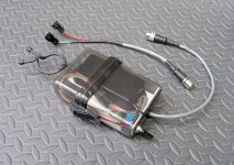
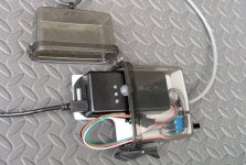
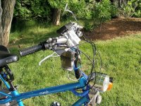
2WD Electric Yuba Mundo Build

Hi Telektik,

Did you check for ground loops? When running 2 controllers from one throttle (with or without CA in the middle), I was informed by Methods that severe ground loop voltage spikes can occur. Especially if you turn the second controller on and off with the first controller running continuously, I can imagine that the second controller momentarily has to fight huge currents.

Please, note that I do not really know what I am talking about here. I am just reproducing other people's knowledge. See http://www.endless-sphere.com/forums/viewtopic.php?f=2&t=33429 and Methods' thread here: http://endless-sphere.com/forums/viewtopic.php?f=2&t=12356
 
hjns said:
Hi Telektik,

Did you check for ground loops? When running 2 controllers from one throttle (with or without CA in the middle), I was informed by Methods that severe ground loop voltage spikes can occur. Especially if you turn the second controller on and off with the first controller running continuously, I can imagine that the second controller momentarily has to fight huge currents.

Please, note that I do not really know what I am talking about here. I am just reproducing other people's knowledge. See http://www.endless-sphere.com/forums/viewtopic.php?f=2&t=33429 and Methods' thread here: http://endless-sphere.com/forums/viewtopic.php?f=2&t=12356

Thanks for the references, but those discussions have been reviewed. The wiring was specifically designed to eliminate ground loops and shield sensitive signals. This does not appear to be the difficulty in this case. In addition, particular care was used prior to the last failure to only switch the controller logic on/off with throttle closed and the wire gauge/power connection layout indicates less than 0.1v steady state difference in Gnd rail voltages with one controller off and the other at Max Amps. There are no indications of disruptive interference with motor/controller operation at any speed.

There is something going on that is not obvious, and the current plan to sidestep the issue by simply not turning the controller on/off will hopefully address the problem even though the cause is unknown. Not very satisfying from an Engineering perspective, but...
 
A Temporary Motor Control Fix

Taxes and other Life Responsibilities ate into tinkering time lately, but I finally got the spare controller installed. This one came with different phase and hall connectors so the usual 5 minute swap was a bit more time consuming than expected. That done, I took the bike out for a 25 miler which was huge fun - I've never run the bike continuously on both motors, and having all that torque on tap at all times is very very cool. Of course the downside of that is that since the power is there, it gets used, so my usual 23Whr/mi jumped to 34Whr/mi with little pedaling. (poor impulse control... :wink: )

Two things occurred to me:
  1. There was an opportunity to make some wiring changes to make the current temporary 2WD-only mode behave more like the original switchable one/two motor scheme
  2. Postponing revision of the motor control wiring until my new CA v3.beta arrives would save reworking the board a second time to take advantage of the new CA features (procrastination = less work)
The 'poor impulse control' issue is actually a little more complicated: I often just run the single motor WOT up small hills or on the flat in traffic sprints and let the CA do the power management. With 2WD engaged, I have to diddle the throttle to try to limit power to two motors as if only running only one. Not good.

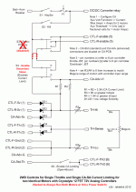
However, since the bike is already wired to limit the power via the CA when on a single motor, it's possible to hack the wiring to always leave the secondary motor engaged but to preserve the 2/1 motor 100%/50% power switching. This would allow running at 50% MaxAmps (1 motor setting) but using two motors where WOT would be CA-limited exactly as before. Since everything is connectorized, it turns out this just requires unplugging a dashboard connector and replacing it with a jumper JST. (Yahoo!) Here's the jumper change to the original circuit:

controls2b.gif
I made the change and gave it a 10 minute test drive this evening and all works as planned - the dashboard 'Select Primary Motor' switch is effectively disabled because both motors are always engaged, and the 'Enable Secondary Motor' thumb toggle is now the 'Hi/Lo' power switch (100%/50% MaxAmps). I can now run the Hi/Lo Power switch exactly as I would have switched one/two motors previously for hills and sprints. This will make it much easier to achieve better range and the Whr/mi results will be more meaningful for comparisons.

Anyhow - I'll be running this way until the new CA arrives. Since I have some pretty fixed 30-40 mile rides where the bulk of the ride is normally on a single motor at 50% power, it will be interesting to see how this new configuration stacks up.
 
Tiny Electronics Board Construction

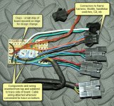
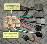
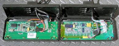
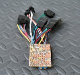
I got a PM about fabbing the tiny board to hold bits of electronics so here's a couple of shots of the old board for the CA v2.23. Instead of making a custom PCB or doing point-to-point wiring, the board is made using a bit of inexpensive phenolic Radio Shack Prototyping PCB that has traces for DIP sockets and runs for power and gnd buses. The parts are laid out to use the existing traces as tie points. Sometimes a small jumper wire is inserted on the component side to tie together traces for additional tie points. The long power and ground buses can be broken into multiple long tie points by cutting the trace using an X-ACTO knife. I prefer to use a Dremel with a small round burr bit to cut the traces - goes very fast. Clean off the flux with a toothbrush and isopropyl alcohol.

The little board in the pics was modded a couple of times but didn't suffer too much from the de-soldering/re-soldering. As you can see, I needed to add some additional parts and so just epoxied on a little extra strip edge-to-edge. The board is easy to cut by scoring a row of holes with a utility knife and bending the length of the scoring gently with pliers or in a vise. A little touch-up on the sander or with a file gives a tidy edge.

No too much to this - it's just a low-tech but easy means to build up small PCBs without too much bother.

30-03-boardTop.jpg
30-02-boardBottom.jpg
Here's a page-size template of the traces on an out-of-box Radio Shack PCB to print and use for sketching parts layout:
 

Attachments

  • RadioShackProtoBoard_276-168B.pdf
    32.7 KB · Views: 163
I got my Mundo in. These things are indeed monsters!

I've got most of the parts in for the conversion, but still need to get a throttle and a few other things. I'm a fan of right hand full twist, but I'm a bit worried the handlebar angle is going to make a twist throttle feel a bit awkward. What's your comfort level with yours, say after a long ride? Would do something different?

Also, how's the controller interface mod holding up? Any updates you've observed?
 
GMUseless said:
I'm a fan of right hand full twist... What's your comfort level with yours, say after a long ride? Would do something different?
I really like the Magura - it's a classic cylindrical full twist motorcycle-style grip. Many don't seem to care for the full twist, but it gives a greater range of motion and better throttle resolution. I sit upright without leaning much on the bars so the unpadded no-frills Magura is quite comfortable. I wouldn't change a thing.

GMUseless said:
Also, how's the controller interface mod holding up? Any updates you've observed?
The current ad hoc controller mod to always run on two motors has worked out great and I'm getting good Wh/mi running two motors limited to the power of one. More on this soon.

Lots of things going on. Converting things to accommodate the new CA v3beta sort of interrupted the motor control revisions, but the controllers are holding up well, the wiring is revised for the new CA v3beta, tests with ghetto wiring of the new style motor controls work fine, and I have the switches to upgrade the thumb toggles to replace the existing 'Boost' switch with a three position 'Motor power - LMH' switch (1/2power, full power, unlimited). I'll be posting stuff shortly...
 
Thumb Toggles

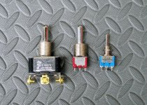
I needed to upgrade the left handlebar thumb toggles with different parts/cabling to accommodate minor circuit changes for power level and motor control - this brought to mind mention in an earlier post of some cool little switches that are great for handlebar controls and crowded dashboards where a robust switch is desired but space is limited. Since I had some in hand for assembly - we had a photo opp - so here's a shot of three equivalent switches (except for current capacity): a relatively standard switch on the left, a standard miniature toggle on the right, and a funny-looking hybrid in the middle that has the large, strong handle of a standard switch but the body of a miniature switch. These are easy to manipulate with gloves and can take punishment from door jambs, branches, etc that would do in the baby switches.

32-02-comparison_iv250.jpg
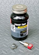
The designations for familiar SPDT on-none-on, SPDT on-off-on, DPDT on-none-on, and DPDT on-off-on are 7101TZQE,7103TZQE, 7201TZQE, 7203TZQE respectively. These have the old standard 15/32"-32 bushing so silicone boots are readily available. They are easy to waterproof by painting the metal-to-plastic and metal-to-bushing joints with liquid tape. For exposed locations like handlebar switches, sleeve the whole switch body with heatshrink for a tidy appearance and to protect the sealant.

32-04-waterproof_iv250.jpg
 
2 Motors at Half Power >= 1 Motor

As mentioned above, in an attempt to avoid further controller issues probably caused by switching controllers on/off on the fly, I recently hacked the controls so both motors are always running but with a Hi/Lo switch that would apply either half or full power via CA limiting (900W/1800W). This setup was just a small modification of the original and continued to use Throttle Override for CA v2.23 control. I had opportunities to make a few 30-40 mile rides to test out the setup but weather and the arrival of the new CA v3beta ended the experiments. Briefly, getaways seemed peppier, low speed acceleration was greater, certain hill climbing was improved, other bike performance was unchanged, and power consumption was largely unchanged. (There is room for great transgression here, but I was trying to ride as before...) On the downside, the bike is slightly noisier with the front motor running all the time – as mentioned previously, the front motor has always been louder, presumably because of the rigid frame in the rear. On bike paths, I definitely prefer the single motor rear drive for reasons of stealth.

This configuration seems pretty attractive considering how very frisky the bike feels while consuming approximately the same power at roughly constant speed and few stop and go situations. Again, these observations are based on limited riding experiences and may be flawed, but at the worst, there was no marked disadvantage to this setup.

It would be great to test a while longer, but the clock is ticking and I need to get the controls finished up so I can move on to CA v3 tinkering and finalizing the battery boxes. The plan then is to revise the controls to preserve the original 'one or two motors with optional Boost' but add new 'two motors with full power, half power, and Boost' capability so testing can be done later. The trick is to get all these modes into a limited number of switches that are comfortable and intuitive to use.

All in all, these controller failures may have been somewhat serendipitous in that the original implementation worked as designed, but that design seems to missed a pretty cool operating mode. All very interesting... :)
 
Motor Control Toggle Rework

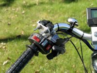
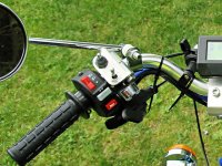
In the midst of reworking the switches for the new motor controls and CA v3, the right thumb toggle mounts were reworked as well. These originally mounted the toggles vertically and it was too easy to accidentally activate the headlight with the ball of the thumb when throwing the Boost switch. Trying different side-to-side and up-and-down displacements were unsuccessful at solving the issue while keeping the toggles comfortable to use. In the end, The switches were flipped 90 degrees so they could be manipulated easily with the entire thumb far from the lighting controls.

38-06_orig.jpg
38-08_revised.JPG
View attachment 3
View attachment 2
In the image above the end of the woven sheath is tied off using waxed dental floss - heatshrink alone is largely ineffective at holding this plastic sleeving in place (too slippery). In this case the end of the sleeve is under the dash and so was left unfinished, but a short piece of heatshrink over the end-tie makes a neat cable. Waxed floss (mint is optional :wink:) is excellent for lacing small to mid-sized cables and can be seen through the sleeve in the same shot as a spiral wrap to hold the wires bundled.

New toggles were refitted to accomodate the new control arrangement which replaces the original 'Boost/No Boost' and '2-motor/1-motor' switches with '2-motor/1-motor' and 'Med/High/Low Power' toggles. The revised scheme offers three different power levels for either 1 or 2 motors. 'High' power corresponds to the old 'Boost' (unlimited) capability and is not used often. This option is the center toggle position which requires a bit more care to achieve. The 'Med' and 'Low' settings correspond to full and half power CA-limiting respectively, are used the most often, and so are at the toggle extremes allowing them to be set easily with a sweep of the thumb.

Unfortunately, the three position LHM switch is an SPDT on-off-on switch and lacks the strong detent action of the DPDT versions. The 'touch' is so light in fact, that the silicone boot tends to pull the switch to center position. I ended up removing the boot until I can order a DPDT on-off-on version or obtain a less rigid boot. This avoids having the boot slowly work the toggle to the center 'High' position and having the afterburners kick in unexpectedly.... :D
 
Preliminary CA v3 Installation

As planned, the CAv3beta arrived in kit form with JSTs and cables to be attached to the unit by the beta testers. The unit has the same case and display board as the v2.23 version but sports a bigger processor board with several additional inputs.

36-02_CA-Compare.jpg
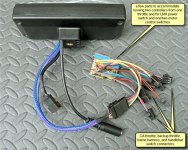
Since there would be many firmware downloads before things settled out to the production version, the unit came with a Tx/Rx connector to tie to a USB/TTL converter cable to reflash the unit. This was a fourth cable/connector in addition to the basic three Speedo, CA-SA power/shunt, and ‘custom’ cables already in place on my v2.23 unit. Unfortunately, the dash is slotted only to allow (three) cables on one side.


The solution was to drop the separate speedo cable and include the extra SP lead in with the custom cable that runs to the tiny electronics board and then break out the speedo cable from there. This gave three cables: Tx/Rx, power/shunt, and custom. As with the v2.23 unit, all cables are relatively short and attach to mating connectors in the dashboard.

A new electronics board was fabbed to accommodate changes to the handlebar switches and to implement the new scheme to run one or two motors without actually powering the controllers up and down as done originally.

36-06a_newCA.jpg
With this new board ghetto wired into place the bike was ridable to begin testing the new CA v3 ;)
 
CA v3 Control Rework

There is an interesting little twist in getting the new CA v3 in place. In the original bike design, the throttle ran to the controllers and the CA achieved limiting using Throttle Override. In that setup, the 'Boost' switch (approx 3000W) simply removed CA limiting by severing the Throttle Override connection and the one/two motor switch set CA limiting to 50%/100% of MaxAmps (950W/1900W) respectively using the CA Vi input. However, to use the nifty new CA v3 features, the Throttle Override hookup used with the v2.23 CA has to be abandoned in favor of running the throttle through the CA proper using the Thi input. This precludes using the original Boost switch strategy – for the CA v3, ‘Boost’ just becomes a very high limit selectable using the same technique as the original one/two motor switch.

To make this work, Plim->MaxCurrent is set to the ‘Boost’ Amps level and the Thi input is used to select lower percentages of this value for normal operation e.g. for two motors
  • High: Boost = 100% = 3100W (essentially 'unlimited'),
  • Med: Full power ~= 61% = 1900W,
  • Low: Half power ~= 30% = 950W.
With this approach it was pretty easy to achieve the original switch functionality and add the desired two-motors-with-power-of-one mode mentioned above. This was implemented in the little board in the preceding post which replaced the original <Boost> and <one/two motor> thumb toggles with <one/two motor> and <Low/Med/High> switches. The delivered power for various switch setting combinations was as follows:

View attachment 1
However, after that prelim setup was implemented, it became clear that a couple of extra parts would allow the same two switches to also provide better Boost limiting for single motor operation as well as give a true low power single motor mode for diddling along on bike paths - a much better solution:

42-02_switchmatrix_2a.gif
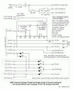
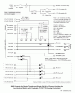
The revised circuit looks like this:

42-06_revisedControls.gif
There are three sections in the diagram above:

  1. The top section provides basic key switch and Kill switch operation for the controllers. S6 and S7 are only provided to allow a controller to be disabled in case of failure.
  2. The bottom section is normally unused and provides a second throttle JST connector that drives the controllers directly in case of a CA failure. A roadside repair involves plugging the throttle into the backup connector. No aspect of the CA is employed and it may be completely unplugged if desired.
  3. The middle section supplies three functions:
    1. It provides a means to disable motors by grounding the Throttle Override inputs of the controllers. This replaces the original scheme that actually powered the controllers up/down on the fly.
    2. A resistor divider composed of R1, R2, R3, and R4 provide the Low and Medium control voltages to drive the CA Vaux input according to the LMH switch setting while pull-up R7 provides the High default control voltage corresponding to the <OFF> switch setting. Trimpot R5 is adjusted such that R1+R2+R3+R4 ~= R5+R6 so that when S3 is switched from two motors to one, the R1-R4 divider will see one half the voltage and so will deliver one half the control voltages to Vaux i.e. one motor gets one half the Vaux LMH control voltages as two motors yielding one half the Amps or Watts limiting.
    3. Resistor R8 drops the value of ThrI->MaxInput so that ThrI->FaultVolt can be set to a value unambiguously greater than ThrI->MaxInput and less than Vcc (~4.99v). Without R8 this new CA safety feature (that prevents runaway WOT if the throttle Gnd wire breaks) cannot be used with resistive throttles (Magura) since in that case ThrI->MaxInput is equal to Vcc and the fault condition cannot be detected.
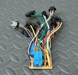
This revised circuit is implemented on a bit of perf board to replace the preliminary 2-trimpot version shown in the CA v3beta installation above.

42-08_tinyBoardTop_iv250.jpg
42-10_tinyBoardBtm_iv250.jpg
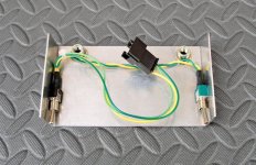
The ‘failure only’ switches S6 and S7 are implemented as tiny subminiature toggles superglued under the rear dashboard cover where just the tips protrude below the bottom edge for emergency use.

42-12_rearCover_iv250.jpg
As shown in the images, R2, R3, and R5 are conventional 20 turn trimpots. Doing a little math, it’s easy to determine the Vaux control voltages for the desired Amps or Watts limiting and use the new CA v3 voltage debug screen (2 left of Main) to monitor Vaux and directly dial in the target voltages with the trimpots. The resulting limiting is pretty much perfect on the first try (I like that screen! ;) ).

After 50 or 60 miles of test rides, the revised motor controls seem to do all that was desired - the one/two motor controller enable/disable functionality is provided by a safer technique, the repositioned switches are easy to manipulate, and the extra operating modes make the bike more drivable without introducing control complications - one switch simply has an extra <center> position.

Attention is now focused on testing the CA v3beta releases... Yahoo! :D

EDIT - This control circuit was modified slightly to support monitoring the motor and power level switches with a Cycle Analogger. See this post.
 
Blinker Beeper

While the dashboard was recently getting overhauled it seemed a good time to try to solve a recurring issue with the turn signals - I often forget to turn them off after making a turn... It's bad enough being an obstacle plodding along the shoulder, but to be an obstacle that seems about to turn into the lane does little to encourage confident and friendly passing maneuvers.

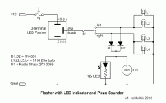
The first attempt to remedy this involved adding a 12v LED indicator to the dash in the hopes that it would catch my eye. Well, not so much. So, as much as I hated to go down this path, I decided to add a piezo beeper. After testing a few, I settled on a reasonably small Radio Shack '273-0059 12vdc 72db piezo buzzer'. This device is small enough to attach to the underside of the top dash panel (Velcro dot) facing downward and is loud enough to hear up to 20 mph but not so shrill it will wake the dead.

EDIT - Radio Shack no longer sells this particular beeper - any other 12v unit may be used...

As mentioned in an earlier post, the single turn indicator is driven using two diode isolators. Normally, a four terminal flasher relay would be used to drive an indicator (no diodes), but there was to be no indicator originally and so a simpler three terminal flasher was used (model: CF13 JL-02). There are 'standard' ways to drive an indicator from a three terminal unit but this diode approach guarantees the indicator will work regardless of turn signal lamp type (incandescent/LED) and isolates the flasher load-sensing circuit so any indicator/beeper load is irrelevant. So - the piezo beeper is simply hard wired across the LED indicator.

Anyhow - works great - no more forgotten turn signals and the beeping is noticable but not unpleasant while waiting at a traffic light.

40-02_flasherBeeper.gif
 
CA Screen Protector

Back in early spring when we were blessed with weather in the 70's, I was riding the Rails-to-Trails quite a bit and made the mistake of wiping abrasive trail dust off my CA screen with my fingers. Very bad plan - the plastic scratched pretty badly with just a single wipe.

When I ordered the CA v3beta I really wanted to prevent this from happening again and figured a screen protector was the plan. It's frankly been a few years since I applied one of these, and it wasn't fun and the results were so-so. I was not looking forward to the application since the CA screen is recessed, not flush like cameras and phones. I started looking at generic kits, but they looked a lot like the one I used back when. To make a long story short, I picked up a ZAGG 'Invisible Shield' for a Samsung Droid Charge at Radio Shack for $0.97 since it was being discontinued - a nice discount from the normal $15 and big enough for two CA screens.

I cut the phone-shaped protector to size using my trusty Fiskars Self-Healing Cutting Mat, stainless straight edge, and a small disposable utility knife with freshly snapped blade tip. A pair of dividers were used to transfer the screen size directly to eliminate measurement errors. The ZAGG comes with a little squeegee, cleaner cloth and a little spray bottle of magic 'application solution'. Following the directions, the protector went on effortlessly with zero bubbles - even with the recessed CA window. A toothpick made a perfect tool to press the corners into place. The magic spray solution goes on your fingers, the protector, etc and works super at allowing things to slide around and preventing fingerprints and trapped bubbles. Quite an amazing application system.

The protector works great - it's crystal clear and seems impossible to scratch. There's some kind of funny thing going on with the light and the slightly textured surface - the color seems richer and the contrast is excellent. My CA v3 is very happy!

ZAGG = Highly Recommended! :D
 
Front Clutch Replacement

I’ve been running with both clutches seized ever since the extended romp with two-motors-as-one about a month ago. I’ll go into the whys and wherefores in a post soon, but they’ve been jammed for several hundred miles. This is not the first time that I have seized the rear clutch but it has always freed itself within 100 miles – but not this time. Pedaling two seized gear motors in DD mode is not huge fun and it's impossible to be stealthy on the bike paths by running one motor because the other is always dragging the rotor rpm up in 1:5 overdrive which is a little noisy. Thankfully, the rear clutch finally freed up of its own accord three days ago, leaving me with just the seized front. Since it was rainy the next day, I seemed a good time to do the repair.

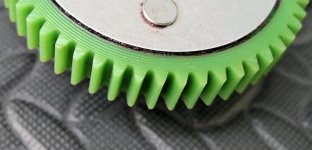
The front motor is a BMC V2S and so has the ‘Green Gears’. I had in hand a replacement V4 ‘Blue Gear’ cluster and a MAC ‘Gray Gear’ cluster. The clusters are interchangeable. All clusters came from Ilia at Ebikes SF with his usual friendly and speedy service. Here are some shots of the three clusters:


  • EDIT: clutch gear assemblies from BMC, eZee, and MAC are interchangeable owing to their common heritage...
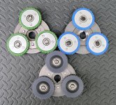
46-02_compareTop.JPG
View attachment 2
46-06_compareSide.JPG
The three clusters use composite gears with different formulations/strengths. The MAC cluster is physically similar to the BMC V2 except that the gears are thicker. Oddly, the BMC ring and sun gears are of sufficient width to drive the MAC planetary gears. The BMC V4 eliminates the riveted components of the earlier design but introduces a plastic cage to retain clutch elements. The single piece design should make the V4 unit more rigid and jam-free than the V2 and MAC clutches but there have been reports of difficulties with the plastic element. The MAC cluster is about half the cost of the BMC V4 version. For no particular reason, I decided to replace the seized BMC Green Cluster with the MAC Gray Cluster.

  • EDIT: New MAC clutches are similar in design to the BMC V4 clutch and seem to be equally strong. They are a tight fit and relocating one of the gear cluster shims to the outer shaft near the bearing may be a good plan. They can be mounted up normally using the outer circlip.
For simple gear, bearing, and seal maintenance like this, there is no need to disassemble the 'inner motor' assembly which simplifies the service procedure in that there are no magnetic fields to overcome or to cause parts to fly together, nipping at fingers. There are good on-line treatments of disassembling hub motors, so I didn’t bother to take any snapshots. Here’s some references:

The whole process was pretty uneventful, but here’s a few points that might be of interest:

Instead of removing and later re-soldering the phase and hall connectors (Andersons and 5 pin JST), I sliced off the heatshrink and slipped the pins from the plastic shrouds (short curved dental pick for Andersons, thin straight dental pick for JST - (eBay - 'dental pick')). The pins fit easily through the various nuts and washers. Re-assembly just required cutting new heatshrink and refitting the connector shrouds.

Here’s a shot of the ‘inner motor’ from the sun gear side (brake rotor side). Before opening the motor, inspect the shoulder area shown and dress out any burrs/dings before disassembly that will cause binding as the bearing slides off the motor shaft. Do the same to the similar shoulder on the other end of the shaft. A little time on this can save needing a puller to dislodge a jammed bearing. Clean the motor shaft and wipe with a bit of grease/oil so the seals will slide off without damage.

View attachment 7
Here’s a close-up of the gears of the seized cluster. This gear has 2250 miles on it and runs smoothly and quietly. Considering the 1500W 35-40mph speeds and hard starts, I expected some damage - but nothing is visible and the teeth appear uniform and largely unworn. Very encouraging – pretty tough gear... :)

46-08_wear2200mi.jpg
This motor has had a torn oil seal on the brake rotor side since last summer and this was a good opportunity to do a replacement. BMC choose to place the seal in a pocket under the bearing on the inside instead of making it a press-in from the outside. This shrouds the seal on the outside from damage, but necessitates pulling the bearing to change the seal. Removing such small bearings often damages them, so a seal swap is likely to require a bearing replacement as well (both were available on eBay). This motor had been built up from V1 and V2 parts and the hub (V1) had a sealed bearing while the cover plate (V2) had a shielded bearing. The damaged seal was in the hub side, but I replaced the sealed hub bearing with a shielded one since the separate oil seal seemed to make a sealed bearing unnecessary.
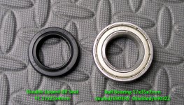
46-12_bearing+seal_notes.jpg
It turns out that the gear cluster shaft key was extremely loose and badly deformed. It appeared about 1mm undersized allowing the cluster to rotate a bit, slamming the key when riding with the clutch seized (regen-like two-directional torque for which it was not designed). Applying the trusty dial caliper to the keyways in the shaft and gear cluster showed a proper size of 5x5x11mm with rounded ends (the shaft keyway was cut with a 5mm end mill leaving the rounded ends). A quick trip to the local Power Equipment Store (snow/lawn care equipment, ATVs, etc - go anyplace that services metric engines) produced a 25mm length of 5x5mm key stock for less than a buck. One end was filed round to fit the recess, the keystock was cut to length, and the other end filed to shape. The new key was shaped with a few degrees of outward taper on the rounded ends so it would jam into the shaft recess snugly when tapped down to seat it. The mating section of shaft was coated with Permatex Anti-Seize Lubricant before sliding the cluster into place over the key and securing it with the snap-ring.

The rest of the reassembly was straightforward. Remember to string washers, nuts, and the torque arm on the wires before re-installing new heatshrink and the plastic connector shrouds.

Here’s some chemicals used in reassembly:

46-14_chems.JPG
  • The Mobilgrease 28 is recommended by BMC and is used to lube the gears: sun, planetaries, and ring. Wipe out the old grease to clear any contaminants.
  • The White lithium grease is used to fill and lube the outer oil seals so they will slide down and spin on the shaft without damage or undue wear. The Lubriplate Marine Lube 'A' shown here is no longer available - it appears to have been replaced with Lubriplate Special Marine Grease (available in 14oz cans for under $10). This grease is extremely tacky, does not dry or cake, is salt and fresh water repellent, and retains lubrication properties even at close tolerances. Other greases can be used, but this is a first choice...
  • Hylomar AF (Advanced Formulation) is a non-hardening sealant specially designed for machined aluminum components (See Industrial Supply Group). I have never seen this used on hub motors but I’m trying is as a substitute for the various RTV and other sealants commonly used. Hylomar AF stays gooey, requires only a very thin film, and can be cleaned up without solvents. I originally gooped the side cover down with Hylomar 2200 miles ago. When the motor was disassembled this time to replace the clutch, the cover came off easily without a puller, and the old sealant was simply wiped off to the bare metal with paper towel and Simple Green – no scraping, etc. So far, I am really liking this sealant – seals great and makes motor service a breeze.
  • When assembling the motor, blue Permatex Threadlocker is squeezed into the hub holes and a VERY thin film of Hylomar put on the cover. The cover is slid down the shaft very close to the hub, the screws inserted and run in half way, then the cover is pressed home. This helps avoid getting sealant on the screw threads where it will interfere with the threadlocker.
  • The Permatex Anti-Seize Lubricant is applied sparingly to the shaft before sliding the gear cluster into place.
Here are some tools to pull the motor apart – these or similar can be obtained from Harbor Freight for very reasonable prices:
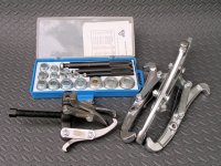
46-16_tools.JPG
  • The big puller pushes the shaft and opposite cover plate out of the hub. As mentioned above, the Hylomar made this unnecessary this time, although I needed it to break the original RTV sealant loose on the first disassembly last year.
  • The small puller is used to pull the gear cluster and can be used to pull a stuck bearing off the shaft. Depending on the tool, you might get away with the big puller for this.
  • The bearing/bushing drivers are used to drive the seals and bearing home by applying pressure to the outer race – a full range SAE set is generally usable for metric installations. A properly sized socket is a workable substitute – be careful not to apply force to the inner race of the bearing.

    As an alternative, you can break the cage (metal ring that keeps the balls separated) in the old bearing by drilling it, peel out the cage, squish the balls over to one side, and lever out the inner race. The outer race makes a respectable driver for flush mount bearings such as this - and since you always have an old bearing, you always have the right sized driver :wink:. For situations where it is necessary to drive a bearing deeper into a recess below the material surface, just dress down the outer surface of the DIY race driver with emery cloth for a clearance fit into the recess.
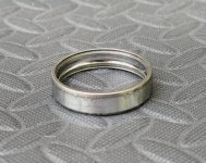
    46-18_outerRace.JPG
After reassembling the motor and remounting the wheel, I re-aligned the BB7 caliper – took 5 minutes (I *like* these brakes ;) ).

Fifty miles later all is working fine - the bike rolls easily and silently again (Yahoo!). The MAC gears whir a bit under power, but that’s not unexpected for straight-cut spur gears (and they are wider). I expect they will quiet down a bit when they’ve been run in.

EDIT: Vent Hole

  • Okay - it's four years after this original post and I've been in these motors several times replacing clutches and bearings. I pretty much do everything as mentioned above except that I stopped sealing the covers. The Hylomar worked great - but - as Justin pointed out, once water gets in from heating/cooling or other means if will work devilment if it can't get out. I had a couple of instances of popping motors open to find a swamp inside. NFG. As J recommended, I vented the covers. I drilled them with 1/16" holes aligned with the inner case edge so water gets flung out. Since the covers were vented, it seemed pointless to seal the covers to the case, so...

    Anyhow, even fording streams with the hubs to the axles, etc and the motors stay nice an dry.

    While I was at it, I center punched a small alignment mark on the flange adjacent to the vent hole to make it easy to realign the cover to the case for reassembly
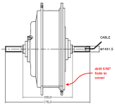
    bmcDrillCover.png
 
What an incredibly thorough and cool thread-you've just answered every question I think I could possibly had about electrifying a Mundo-THANK YOU!
I only have a rear Amped bikes motor, so I won't have quite the speed your baby does, but with all that you've written here I can do it with some confidence now instead of fumbling around for parts.
Again-Thank you! and Happy Riding!
 
I Want an Analogger…

I’ve been waffling over purchasing a Cycle Analogger for some time but the new CA v3 rework prompted me to finally take the plunge. With the CA v3, the Analogger records these parameters each second:

  • Ah,
  • Volts,
  • Amps,
  • Speed,
  • Distance,
  • Temperature,
  • RPM,
  • HumanWatts, and
  • Torque(Nm)
Unfortunately this bike makes data interpretation a little more troublesome because of the six motor/power level combinations that might be in play at any given time (one/two motors, lo/med/hi power). However, inspecting the Analogger manual revealed that the unit has two optional analog inputs in addition to the serial data input and that these are sampled and the results written whenever a new data line is received from the CA. These can be used to detect and record the settings of operator thumb toggles. Very cool. 8)

Voltage Snafu

The only difficulty is that the Analogger inputs have a max voltage of 3.3v and the recently reworked motor controls were set up with a max voltage of 5v. Because of the resistor dividers on the controls, the only two workable choices were to either use resistor dividers on the two Analogger inputs, or regulate the 5v supply down to 3.3v to run the control dividers with a reduced voltage (yep – I’m looking for a simple passive component solution…)

The input divider approach proved problematic because in order to avoid disrupting the existing dividers, the input dividers had to use large value parts which yielded the usual noisy signals from the high impedance antenna effect. Not good.

Regulating the 5v supply turned out to be the solution of choice, although this had an annoying twist because of the low current restriction. Superb regulation isn’t necessary for this application so a simple zener regulator is fine except that the average off-the-shelf zener has a zener current (Iz) of 20ma to get around the knee of the curve so it can develop the specified reverse voltage. According to ebikes.ca, the CA v3 regulator is rated for 1.5W so with a fresh-off-charger battery voltage of 73v we get 1.5W/73v ~= 20ma. The CA v3 draws 10ma internally, leaving an absolute max of 10ma available for use for Iz, throttle, and Vaux circuits. With a ballpark current requirement in hand, a quick search on Mouser turned up a zener (TZX3V0C 3.1-3.3v) that would work comfortably with Iz = 5ma

The original controls circuit used a resistor to drop the throttle voltage to take advantage of the new CA v3 feature to detect broken throttle Gnd wire but that part could be eliminated by driving the throttle from the 3.3v source. The Magura is about 5K, the control divider is about 3K, so we need about 3.3v/5k + 3.3v/3k = .66ma + 1.1ma ~= 1.8ma. For Iz = 5ma we need 5+1.8 = 6.8ma total so starting with the CA 5v supply we need an Rz of (5 – 3.3)v/6.8ma = 250ohm or 220ohm using a stock part value. Checking: (5-3.3)v/220ohm = 7.72ma which is less than the 10ma max we have available. Okay.

A more power-thrifty solution would be to use an LM-385-ADJ adjustable micro-power regulator which would cut the draw by near 5ma by eliminating the need for Iz.

Controls Rework for 3.3v

Unfortunately, the selected zener wasn’t available locally and I didn’t want to pay minimum shipping and wait for Mouser, so I substituted from parts on hand – a 2.5v micro-power voltage reference (LM385-2.5) in series with a forward-biased silicon diode yielding a 3.22v reference. I super-glued an extra bit of perf board onto the end of the electronics board to hold the two extra parts. The updated controls diagram is shown below using the proper zener instead of my kluged substitution:

48-01_controls.gif
(The original discussion of this design can be found in this post.)

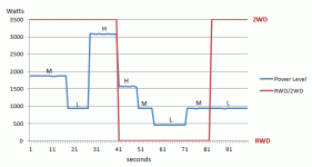
Collecting a minute or so of data while flipping the thumb controls yields the graphic below after a little Excel manipulation. Note how 2WD/Low limits the CA to same power level as RWD/Med – this is the two-motors-as-one mode added recently.

48-18_dataLog.gif
48-20_switchmatrix_2a.gif
 
Packaging the Analogger

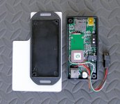
The Analogger is actually smaller than the large screen CA but is not sealed and has a switch, USB port, and removable micro-SD card slot. The Analogger manual suggests tucking it away to protect it from the elements and also calls out the mechanical sensitivity of the SD card slot mechanism. Not too good for trail dust, rain, etc. There are no connectors or openings for the extra two analog channels, making using this a solder and drill DIY affair. There are two connectors: one for power and one for the serial data stream – the extra analog data requires a third connector. In short, the Analogger is ruggedly constructed but is a ‘Sunny Day’ design that needs a bit of DIY tinkering to be trail-ready. The manual calls all this out so no surprises or complaints ;)

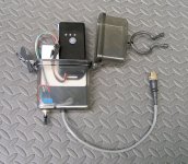
Since the device was going to be a ‘use sometimes’ gadget and since reading the data via USB is easier than removing/handling the tiny micro-SD card, I wanted an easily removed mounting scheme that would somehow fit on or near my already cluttered handlebars. I opted to box it in a weatherproof case, hang the case from the handlebars, provide an external power switch, and direct-wire a single connector to carry the power, serial data, and analog data.

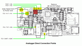
The five direct connections are brought out to a mid-stream JST connector so the Analogger can be detached from the clear plastic case. Instead of drilling the Analogger case to bring out the new leads, it’s simply notched so the PCB can be removed for easy bench work. As noted in the Analogger Manual, I removed the two pull-up resistors R8,R9 which are installed primarily to support direct connection of thermisters. Without the resistors, high impedance voltage sources can be monitored.

There are available pads for all leads except power (+). However, the female power connector uses through-hole mounting and it is easy to reflow the solder on the end pin and slip a lead into the large mounting hole.

Normally the signal and power grounds are distinct (a resistor connects them) but in this application, they both reference CA-Gnd so a single Gnd lead was shared. This isn't the best practice in general, but since there are only 5 distinct voltage levels of interest, a bit of noise was not an issue (and the mini-XLR connector on hand was only 5-pin - no extra pin for a signal Gnd :wink: ).

AnaloggerDirectConnections.gif
View attachment 7
A quick trip to Sports Authority turned up a nifty box (Lifeline Weather Resistant Case model 4430) and a black twisty tie (Nite Ize 6” Gear Tie GT6-2PK-01) to hang the box from the bars. An 5-pin mini-XLR connector for Crystalyte hall sensors from the parts box did nicely for the connector. I mounted the Analogger on a small piece of .060mil styrene plastic from the hobby shop (Evergreen Scale Models plain white 6”x12” sheet item 9060) using 3M automotive emblem tape (auto stores, etc - used to mount emblems and trim on car bodies forever). A round clear vinyl bumper from Home Depot stuck on the front of the Analogger wedges it snugly into the case. The cable is tie wrapped to an extra rectangle of plastic on the bottom that acts as a removable strain relief so the case can be freed and slid down the cable by removing just the switch retaining nut.

I had a bit of an electrical loading issue with the controls when the Analogger was switched off and the inputs changed to a low impedance, upsetting the resistor dividers for bike controls. Since I had a 3PDT switch on hand, I opted to just open-circuit the two inputs when the powering down the Analogger.

48-04_boxed.jpg
View attachment 5
48-08_slideOut_iv350.jpg
48-10_assembled.jpg
48-12_USB.jpg
48-14_installed_iv350.jpg
View attachment 2
The assembled unit works great. I get about 0.01v – 0.02v of noise from the monitored resistor dividers for the thumb switch controls which is in the neighborhood of 1% - fine for this application. Separate signal grounds for thermister use would likely bring the noise down near the expected 1/2bit out of 10 bits ADC resolution over 3.3v or a bit less than 0.002v.
 
I love your yuba and am envious of your skill set to make it so functional and good looking.

Currently I am rocking a mid drive with a mac , but honestly I want to push more power thru it then It can take.

Considering adding my 5404 or 3525 to the rear so I can feed as much voltage that I want..

You were right about the handle bars they did grow on me. Thanks for sharing.
 
ohzee said:
Currently I am rocking a mid drive with a mac , but honestly I want to push more power thru it then It can take.
Considering adding my 5404 or 3525 to the rear so I can feed as much voltage that I want...
I certainly understand the feeling - I'm a compulsive speeder by nature. With my current 20s2p battery pack I get about 38-39mph sitting upright but the two gear motors are pretty loud when flogged at 3kW.

I'd like to go DD for a quiet road machine, but I think I see a lighter frame MAC build for stealthy bike path use as my next effort - it's hard to get away from the freewheel for unencumbered no-assist pedaling...
 
Hey Tek,

Having had some road time, what's your thoughts on your Torque Arm implementation?

I've got Kiwi's plates, which work great if I don't use Regen. The minute I engage regen, my hub (9C 2810) works it's way loose after 10 to 20 hard regen cycles. I'm considering some mods now, maybe using the slotted washers that Yuba sells, or perhaps the Amped arms you've got. One problem I have is that there's so much room in the drops outs, there's nothing to really guarantee proper wheel alignment. I was thinking the slotted washer might address that.
 
GMUseless said:
Hey Tek,

Having had some road time, what's your thoughts on your Torque Arm implementation?

I've got Kiwi's plates, which work great if I don't use Regen. The minute I engage regen, my hub (9C 2810) works it's way loose after 10 to 20 hard regen cycles. I'm considering some mods now, maybe using the slotted washers that Yuba sells, or perhaps the Amped arms you've got. One problem I have is that there's so much room in the drops outs, there's nothing to really guarantee proper wheel alignment. I was thinking the slotted washer might address that.

That's too bad to hear as I have some kiwi adapters in the mail. I was considering using my 5404 on my yuba.

You using nord-lock washers also ? Wonder if that would help any.

Curious what you come up with.
 
GMUseless said:
Having had some road time, what's your thoughts on your Torque Arm implementation?
The torque arm arrangements have worked out very well. I've got about 2500 mile on them now and they hold perfectly - no movement or loosening - no Nordlocks. I've had them both out for brake/motor tinkering and the dropouts and TA components show no deformation at all. I run the BMCs up to about 1550W each.

I clearly don't have regen, but my seized clutches did put a fair drag on the axle with the 1:5 overdrive effect when I coasted or ran with a motor shut down. Also, the bad front cluster key I had recently was giving me a hard impact on re-engagement that was a bit like an impact driver on the TA. Again, after hundreds of miles of this, no adverse TA effects.

GMUseless said:
One problem I have is that there's so much room in the drops outs, there's nothing to really guarantee proper wheel alignment.
I'm not sure I quite understand that. My axle fits pretty snugly in the slot and the wheel is aligned if I slide it to the end of the slot. Back in the original post, I described having the washers machined to allow me to do this. Is your axle 14mm or less? If you have 12mm axle, you may have problems with the Mundo washer since they are designed expressly for 14mm shafts and rely on the 14mm dropout slot to position the axle vertically.

Here's a post about mixing Mundo washers and Kiwi plates.
Here's a post about addressing smaller axles.

One possibility is to drill the Kiwi plate and dropout, and run in a bolt to hold the plate in place against the chain stay. And, of course, there is always Doc's DP-420 epoxy...

I'm thinking a PM to Kiwi may be in order to get some authoritative advice... :)
 
I've got 14mm axles. When I mentioned the alignment, it was in terms of the axle shifting from the top of the dropout...again caused be some looseness introduced by the regen. Definately not a safe situation.

Thanks for the links, it makes sense that Kiwi's plate require the axle to be all the way into the drop out, and the Yuba washers would prevent that.

I like your idea of bolting the plate into the drop out. Perhaps a bolt at the tip of the front and rear triangle. I'll have to look at the frame to see how that might affect things. I'll PM Kiwi, mention this thread, and ask him if he's got any ideas or comments. I know Philistine has had a similar problem with the plate and strong regen...which he mentioned in his fork failure thread.
 
Back
Top