12 kw rc motor

Arlo1 said:
In order to get more power you need more power going in or a higher efficiency which one is it?
If we're still on the pole count comparison....... For the same power, in each case - more poles gives you less speed for the same volts and more torque for the same amps.

It doesn't get you more power, neither does it stop you getting as much power as you would from running the motor faster with fewer poles.

I'm just repeating what bearing has already explained, though.
 
Ok are you saying it makes it he same power at lower rpm so this is where more torque comes from? But are we talking magnet polls? Or stator teeth? So same power at lower rpm is a good thing and as far as hitting a max power number it will be the same because the erpm with be the same at the max rpm with both numbers only the higher magnet count will be less mechanical rpm so less bearing losses.
 
bearing said:
With 28s poles you don't need to take it to 9000 RPM, because it will make the same power at 6400 (9000/6400 = 28/20). And it will have the same losses. EDIT: and the same electrical frequency. And the same amps. And the same battery.

I can not make my point any clearer.

I believe you are incorrect.

A motor with more poles will not be capable of more torque vs a motor with fewer poles for a given motor size. (sure it could make a bit of difference, but it is not very much)

If your motor speed is being limited by commutation frequency, or other limitiations of the controller, due to the high pole count of the motor then fewer poles will allow you to spin the motor faster at the same torque, giving you more power.

Also high pole count will increase the core loss (all other things being equal) due to higher frequency magnetic field changes in the iron (hysterisis loss).

A good design is a balance of multiple factors, the number of poles is a pretty big factor.

-ryan
 
Thanks Ryan. I was going to PM you... I was getting told 2 different things..... I am simply trying to help make a motor more usable for off the shelf controllers for the DIY crowd. Because as you say its about the package.... YES making a uber bad ass motor is cool BUT when controllers become harder to find its not worth it!.
 
Biff said:
A motor with more poles will not be capable of more torque vs a motor with fewer poles for a given motor size

That used to be my understanding too, but it changed pretty recently after thinking it over again during a discussion on endless-sphere. And I was apparently so convinced that I now see it as truth. But you may be right. It would be pretty strange if you could just increase the pole count until you have a motor making it's peak power at bicycle crank RPM.
 
I always felt uncomfortable with the "electrical gearing" thing. How is torque multiplied etc..? Eventually I succumbed to the argument that if increasing the pole count reduced Kv then you must be getting more torque per amp, somehow. Is Kv not inversely proportional to pole count, then?
 
Why would pole count change torque? It's the same amount of magnet area put to work. Increasing poles would seem to only increase frequency as long as it's not somehow getting the poles to make the commutation better by lining up with the slots. In the case of this motor guys are talking about running at the frequency limit, so increasing frequency for the same motor rpm has to decrease potential power and efficiency too at a given motor rpm due to increased core losses.

While so many experts are visiting, can someone explain why brushless commutation is good. Brushed motor commutation seems better to me (ignoring brushes) due to the nice alignment of the coils with the magnets all the way around the motor. Brushless motors have a skewed alignment due to the different number of slots and magnets. It would seem that that timing determined by the halls is only perfect for one pole pair and one slot with the others out of perfect alignment. With hall or optical sensors able to make brushes unnecessary, why don't we see any brushless motors in a brushed motor alignment? Aren't brushed motors able to make more torque for a given size due to their better use of the magnetic forces instead of 1/3 of the coils sitting idle at all times?
 
John in CR said:
While so many experts are visiting, can someone explain why brushless commutation is good. Brushed motor commutation seems better to me (ignoring brushes) due to the nice alignment of the coils with the magnets all the way around the motor. Brushless motors have a skewed alignment due to the different number of slots and magnets. It would seem that that timing determined by the halls is only perfect for one pole pair and one slot with the others out of perfect alignment. With hall or optical sensors able to make brushes unnecessary, why don't we see any brushless motors in a brushed motor alignment? Aren't brushed motors able to make more torque for a given size due to their better use of the magnetic forces instead of 1/3 of the coils sitting idle at all times?
No.


for a more elaborate answer, see next post.

:mrgreen:
 
John in CR said:
Why would pole count change torque?
There are many ways to explain that. One is that kv changes, since more poles will act like a higher RPM. So it will generate more EMF at a fixed RPM. And if kv changes, then kt changes, which means more torque for the the same currrent. But what Biff said, that maximum torque doesn't change with more poles, made me hesitate. I'm going to run a few simulations to see what conclusions I can draw.
 
Even Ryan concedes that more poles will give a "bit" more torque. How is that achieved?

From Handbook of Small Motors. Hansellman, Yeadon et al - Chapter 5:
 

Attachments

  • Design-parameters.jpg
    Design-parameters.jpg
    48.2 KB · Views: 1,717
I spent some money and bought credits for the simulator at http://www.emetor.com/
(You can try it for free, but it only will simulate with linear materials, i.e. without saturation.)

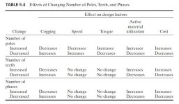
In another thread I found dimensions for the stator and rotor of the ca120, measured by toolman2. I put those dimensions in the simulator, with a 60mm width, because I read somewhere that the colossus has the same stator as ca120, but with twice the width (however, dimensions doesn't match the drawings in the sale thread of the colossus). I also put 4mm back iron on rotor (instead of 1.75mm), because I noticed that the back iron was saturating, and I thought (hoped) that maybe the colossus will have a thicker back iron than ca120. Thickest stator sheets available in simulator was 0,27mm thick Sura NO27, so a bit thinner than 0,35mm, which means the iron losses will not match reality.

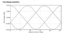
I simulated with 20 and 28 magnets at 3000rpm. I only got a "no load simulation" to work, so I could not try different currents with load to see what would happen. I will report back if I get the "load simulation" to work. I can give you my setup files for the simulator if you are interested. Attached are the results of my simulations with 4mm back iron. (edit, I also added the ones with 1.75mm back iron)

Short story: (which doesn't tell the whole story, because the BEMF shape has some interesting differences)
Code:
Motor				 Fundamental peak phase back-EMF:
20p 1.75mm iron	31.37V
20p 4.00mm iron	35.00V
28p 1.75mm iron	38.12V
28p 4.00mm iron	40.21V
 

Attachments

  • colossus-20p-3000rpm.pdf
    548.1 KB · Views: 64
  • colossus-28p-3000rpm.pdf
    574 KB · Views: 82
  • colossus-28p-3000rpm-4mm.pdf
    584.7 KB · Views: 74
I allways assumed it is the shorter angular moment on the shaft that would allow slightly varying degrees of tourque for a given dimension.

its prolly quite minimum on an optomised design.

example 1: 12 slot 7 pole= 1.71 degrees of "off set" from tooth to pole center, on the next comutation cycle
example 2: 12 slot 5 pole= 2.0 degrees of "offset" from tooth to pole center, on the next comutation cylcle

example 1 has a therotical 15% distance advantage over #2.....there are a ton of variables & these examples are very closly matched (they are prolly unmeasurable as the slots are prolly already in the sweet spot of the PM flux feilds when switched)

any thoughts on my observation?
I would like to know if I am totaly not seeing something here.

run the examples on motors with more extream variance in the pole pr counts & it becomes more pronounced.....untill you re-calculate the winding senario's & measure the angular ratio's that a comutation cycle is traveling.

Its there that the "magnetic gear ratio" nonsence comes from:
example 1 requires 7 (or something like that) comutation cycles for 1 revolution of the rotor
examlpe 2 requirers 5 (again spit balling....) comutation cycles for 1 revolution. (in theroy higher kv on the same stator....slightly less kt potential geometricly speaking)
 
speedmd said:
It's the same amount of magnet area put to work

Not sure this is correct.

The more poles and teeth, the more gaps you have, and the less area you have to work from assuming the gaps are the same size in the low vs the high count motors.
Were are assuming same magnet fill percent. So it will be same magnet area. Remember you can have 100% magnet fill.
 
Arlo1 said:
speedmd said:
It's the same amount of magnet area put to work
Not sure this is correct.
The more poles and teeth, the more gaps you have, and the less area you have to work from assuming the gaps are the same size in the low vs the high count motors.
Were are assuming same magnet fill percent. So it will be same magnet area. Remember you can have 100% magnet fill.
But the total flux leakage will still increase with pole count.
 
Thud said:
"magnetic gear ratio" nonsence

Probably not nonsense. You obviously get more torque (per amp) with more poles, with no penalty in added winding resistance. But the peak "saturated" torque might not rise with more poles, if Biff is right. So if you are looking to use the motor at the absolute max, more poles may be a disadvantage. That's how I conclude the latest "news" on endless-sphere :D
 
bearing said:
...You obviously get more torque (per amp) with more poles, with no penalty in added winding resistance.

Bearing,

Can you explain the obvious part, down to a level where I might be able to grasp it. How does it show up in the pdf's you shared? Is it in the flux density section or the way the back EMF seems to fit better with 28 poles? Doesn't the flux linkage waveform look much better with the 20 pole?

John
 
bearing said:
Fundamental peak phase back-EMF:
20p 1.75mm iron 31.37V
20p 4.00mm iron 35.00V
28p 1.75mm iron 38.12V
28p 4.00mm iron 40.21V
[/code]
So maybe a 20 magnet setup will be better with a trap or 6 step type controller (cheep china controller) vs the more of a sine looking wave from the 28 poll setup.... I only compared the 2 4mm motors IM sure the other 2 will be similar.
 

Attachments

  • 28 poll 4mm.JPG
    28 poll 4mm.JPG
    23.9 KB · Views: 1,623
Arlo1 said:
bearing said:
Fundamental peak phase back-EMF:
20p 1.75mm iron 31.37V
20p 4.00mm iron 35.00V
28p 1.75mm iron 38.12V
28p 4.00mm iron 40.21V
[/code]
So maybe a 20 magnet setup will be better with a trap or 6 step type controller (cheep china controller) vs the more of a sine looking wave from the 28 poll setup.... I only compared the 2 4mm motors IM sure the other 2 will be similar.

If you look at the BEMF waveform, you can see that the 28 pole has a much more trapezoidal shape. So to me, it looks like the 28p is more suited to 6-step controller.

I don't know what flux linkage is, to be honest.
 
Back
Top