15S LiPo charger using DC DC converters

If the source for 5V converters has dried out, search the 1.8V version and put two in series for each cell 8)
The datasheet usually states +10% adjustment range; which is roughly 4V for two converters.
Then use milliohm-resistors for the sense inputs to push it a bit higher.
-Olaf

<edit> found one , but I'm not sure about stock quantities:
http://cgi.ebay.de/SynQor-Qtr-Brick-48V-In-1-8V-Out-DC-DC-Converter-/190450503997?pt=LH_DefaultDomain_0&hash=item2c57bc113d

<edit 2> for experiments a dual output version 3.3v and 1.8v @15A
http://cgi.ebay.de/DC-DC-converter-36-75V-1-8V-3-3V-out-15A-each-/160491524179?pt=LH_DefaultDomain_2&hash=item255e0a5053
 
Hyena. I think you will find it charges so fast with these you wont want to bulk charge with a meenwell anymore!
 
The thing is, parallel charging at the pack level with a meanwell never sees my packs get any more out of balance than a delta v of 0.03v. Even after months of not balancing. I bulk charge my pack now at ~20 amps so it wouldn't be much faster but it's best to be on the safe side though
 
Hyena said:
Like Arlo I after a quick look on ebay I could only find the 3.3v ones on ebay and I'm guessing they don't have enough adjustment range to get up to 4.2v?

My plans are slightly different - I was going to use a meanwell to bulk charge almost to full pack voltage - say around 4.1v/cell and then have a series of these little dc-dc converters to top it up to 4.15 or 4.2v. This would enable the pack to still be charged fairly quickly but nicely balanced as well with the lowered powered dc-dc converters. These gutsy little ones could do the whole job though.

Arlo, keep us posted if you find any good cheap 5v ones like Jeremy is using. His original link is dead now but I assume they're from the Israel seller that's selling other varieties of these things on ebay.

Hyena,

Be aware, there are a number of just alike boards by companies like Lucent, CD Technologies, tyco, Wall industries and others. The pin out and functions seem to be identical.

I found these SynQor boards with a simple "DC to DC 5 volt" search string. More then 10 listed, eBay number 300368555195. $7.99 each. Also try 48 dc dc converter for good results. A lot of these are a little more costly but they have installed heat sinks. These things do get HOT. so the extra is worth it

Jim
 
olaf-lampe said:
If the source for 5V converters has dried out, search the 1.8V version and put two in series for each cell 8)
The datasheet usually states +10% adjustment range; which is roughly 4V for two converters.
Then use milliohm-resistors for the sense inputs to push it a bit higher.
-Olaf

Olaf,
Be aware, there are a number of just alike boards by companies like Lucent, CD Technologies, tyco, Wall industries and others. The pin out and functions seem to be identical.

I found these SynQor boards with a simple "DC to DC 5 volt" search string. More then 10 listed, eBay number 300368555195. $7.99 each. Also try 48 dc dc converter for good results. A lot of these are a little more costly but they have installed heat sinks. These things do get HOT. so the extra is worth it.

They say the adjustment range is 20% down and 10% up so for a 5 volt board you can get 4 to 5.5 volts.

Jim
 
We finished the assembly and wiring of the individual charger boards and gave it its first test as a complete assembly. I even have the Cell Log wiring on the pack. All 51 wires are tapped into the charger boards. I used a 68 pin scsi cable that had 26 awg wire in it. We just need to make the top cover and attach the most positive and negative cables that will route to the 800 amp breaker.

Guess what? It WORKS ! ! ! It even looks good !

We hooked up a 48 volt set of 32 amp hour (two 16s in parallel) Hawker to the 48 volt buss as a dump pack and powered it up. The charger board are set to 3.5 volt output and the resistor coils limit the current to the batteries to about 3 to 5 amps per cell stack, depending on the cell voltage.

The parallel cell stack voltages were all over the place from initial testing. They varied from 3.2xx to3.34x. The resistor coils we added to the charger boards kept the current to a reasonable limit, about 30 amps in the 48 volt buss. The charger boards kept the current steady as the cell voltages started to rise. We then added a 48 volt battery charger to the battery pack to keep the dump pack somewhat stable.

When the the cell voltages started to cross 3.40x volts the current had moderated on the higher voltage cells while the lower voltage cells were still getting higher charging currents. At about 3.450 volts, all of the cells had pretty much matched. I had to leave at that point. Darin will allow the cells to reach 3.5 volts and then shut down the charger and let the pack normalize.

Darin thinks it will settle at 3.35 to 3.36 volts. I'm hoping for closer to 3.40 volts. I guess I'll find out when he emails me tomorrow.

We are going to set the battery in the tractor Tuesday night to fit up the mount points and seat mounts.

Photos and more info later.
 
I just ordered 30 of these http://cgi.ebay.ca/ws/eBayISAPI.dll?ViewItem&item=300368555195&ssPageName=STRK:MEWAX:IT
I think they are the same part # as what jeremy got. There is 5 more left and 20 hours on the auction!
 
Arlo1 said:
I just ordered 30 of these http://cgi.ebay.ca/ws/eBayISAPI.dll?ViewItem&item=300368555195&ssPageName=STRK:MEWAX:IT
I think they are the same part # as what jeremy got. There is 5 more left and 20 hours on the auction!

IMHO these are different, they are QNB-types, but their link to the datasheet refers to Jeremy's QNA type. The parts I got from from Israel aren't potted. Maybe that's the only difference? You should search for the propper datasheet and check, if they have an isolated output and/or synchronous rectified output. Otherwise they could end up in smoke, when you try to put them in series.
-Olaf
 
olaf-lampe said:
Arlo1 said:
I just ordered 30 of these http://cgi.ebay.ca/ws/eBayISAPI.dll?ViewItem&item=300368555195&ssPageName=STRK:MEWAX:IT
I think they are the same part # as what jeremy got. There is 5 more left and 20 hours on the auction!

IMHO these are different, they are QNB-types, but their link to the datasheet refers to Jeremy's QNA type. The parts I got from from Israel aren't potted. Maybe that's the only difference? You should search for the propper datasheet and check, if they have an isolated output and/or synchronous rectified output. Otherwise they could end up in smoke, when you try to put them in series.
-Olaf
Thanks for the heads up I will do so. I already ordered them and payed but I did get tricked by the data sheet they linked me to. I looked at his ebay listing and he says they are isolated outputs from the imputs. So I should be ok.
I will let you know when they are here.
 
Howdy all,

We did "JUST" get the battery in the tractor Tuesday night. First we had to make up a non conductive lifting strap. We had also gone to the Lowes to get some Lexan to make a cover so it was late when we set it in the frame. Should be back to work on it again Friday night. If I do go, I'll get pictures.

Another milestone past, Got the cell log monitoring system wired to the mounting board (see photo). Man 51 26 AWG wires by color code to 7 plugs to 7 cell logs. Tiny little things, not good for old eyes and shaky hands. Took 90 pins to make up the 51 connections, glad we ordered 100.

Got lucky with the pin crimping tool, Darin had one he didn't even know about. I was just going on eBay to buy a used one for $200.00 when he stumbled across it.

The picture shows only six cell logs, unfortunately an OOPS moment with one of the ones we had on hand let the magic smoke out. Of course since I didn't order in a spare, they are now on back order. Got a couple on order, just have o wait.

Right now there is a piece of rolled masking tape under the units since I couldn't find my roll of Velcro strips, Once I get them properly stuck down they will look better.

I'll remove them to circuit test the harness, then we can plug in them and set all of the parameters. What a cool way to monitor charging and condition. I have an extra a 200V digital voltmeter so I'm going to use one of the spare pairs in he scsi harness to add so we can monitor that as the battery charges and get a quick estimate of SOC.

We are going to bend up the battery cover Lexan so we know where to mount the seat and circuit breaker now that the battery is in.

The 10 x 18 inch piece of heat sink just arrived, it will be mounted above the motor and will have the controller, (Open ReVolt until ours is finished.) contactors, reversing contactor, and other stuff. A quick test drive with Video Of Course.

Once that's done we strip it, paint it, assemble it and PULL.

Jim
 
Untitled-1 copy - Copy.jpg

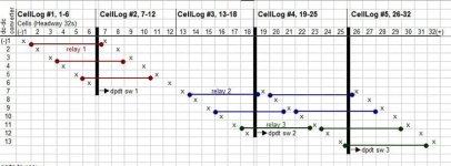
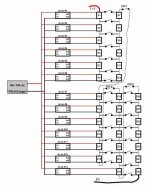
I'm upgrading my pack to 32s lifepo4 and use 13 dc-dc converters mounted on board to charge the cells grouped in parallel. Ideally it should be 1:1 but I can only fit 13. This takes care of the hvc function - which is an almost leave and forget charging/balancing.
The dpdt switches are used to disconnect the series connections and powers the dc converters thru the Cosel psu. The psu also connects to the 12v converter and energizes the relay to parallel the balancing wires as shown in the pic. All the CellLogs are "on", although only CellLog #1 or 2, and #5 monitors the cells, the rest are redundant.
A drawback is cells #13-31 will be late about 30-40 minutes from being fully charged compare to the other cells but I think is still worth it because of the ease of use. Max discharge current is limited to 30A, so the S-822 switch is fine.

parts to use:
- 3 pcs. dpdt switch , NKK S-822 30A
- 3 pcs. 4pdt relay , Omron MY4IN-D2
- 12v dc-dc converter(300mA +) to energize relays
- 5 CellLogs
- 16 pcs. 5A+ resetable fuses
- 13 pcs. VSX40MD23-U dc-dc converter
- switching psu rated 36v-72v , Cosel ADA600F-36
- 16awg, 18awg wires
 
Nice.
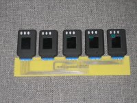
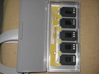
Wiring up all those CellLogs can be a pain. On a similar project, I made a PCB to handle all the CellLog connections. I found some board mounted connectors that fit the CellLogs and ran everything to a ribbon cable. This made for easier construction.
IMG_0009.JPG
 
fechter said:
Nice.
Wiring up all those CellLogs can be a pain. On a similar project, I made a PCB to handle all the CellLog connections. I found some board mounted connectors that fit the CellLogs and ran everything to a ribbon cable. This made for easier construction.
View attachment 1

Fetcher,

Very nice, I like the way it came out a lot. Much cleaner and much more robust then what I came up with. I'll be building something like this for our system to be swapped in when mine fails (which it probably will soon).
 
olaf-lampe said:
Hi Fechter,
looking good!
I would isolate the pcb with a decent spray. Not funny, when the traces get shorted somehow... :(

-Olaf

In the end, the board was mounted in a plastic box and there is a sheet of clear polycarbonate over the top of the traces (hard to see in the picture).IMG_0024.JPG
 
I'm limited to available space, not too the # of dc-dc converters. So they have to be distributed to other packs by parallel switching. What are the drawbacks?
Relays will be mounted in a shock-absorbing material and protected from the elements. Charging is monitored thru CellLogs. Six 4pdt relays are used to parallel 22 connections.

The function of switches #1-3 are as follows, the rest of the switching are done thru relays:
SW1 - disconnects series connection and powers 2 relays to parallel cells 1-12
SW2 - disconnects series connection and powers 2 relays to parallel cells 13-24
SW3 - disconnects series connection and powers 2 relays to parallel cells 25-32
 

Attachments

  • distributed charging & balancing using dc-dc converters copy.jpg
    distributed charging & balancing using dc-dc converters copy.jpg
    70.7 KB · Views: 1,853
Has anyone thought of using LED-drivers as cc-charger in combination with a HVC-board or cellLogs?
There is a ELN30 series from meanwell that looks promissing. No need for a 48V power supply, just hook it up to the grid. i hope the outputs are isolated and ready to be series connected...
http://www.meanwell.com/webnet/search/seriessearch.html#led
http://www.meanwell.com/search/eln-30/default.htm

-Olaf
 
I'm using an On-On type. I cannot trust myself to always manually check connections all the time cause of sometimes being absent-minded or preoccupied...
perhaps there is an automated way where a certain module can check if the series switches are closed/open, and then decides the switching of the relays.
 
Back
Top