Build your own charger

ElectricGod said:
john61ct said:
Looking for very robust & reliable NO relays happy to switch off an active buss with 40-60A flows, high cycle lifetimes, very unlikely to fail closed.

Ideally very low parasitic draw while sitting open.

Willing to wait from China if cheap enough, qty few dozen at a time.

I have noooo idea what you are looking for!
You'd have to actually say what you are wanting to do and why. One sentence just isn't enough info.
Sorry most likely I don't know enough to phrase it properly.

See if my OP here helps

https://endless-sphere.com/forums/viewtopic.php?f=14&t=98599&p=1444529#p1444529

and let's carry on there rather than divert this thread any further.
 
ElectricGod said:
SSR's usually cost more than triacs for the exact same amount of current handling. There's no real gain there. Also an SSR is just a mosfet junction...might as well use mosfets instead for less cost. The triacs will all be at the same potential...aka 120v AC. Turning on 1 triac gate or all the gates does not create any variance in the potential voltage across any specific triac. Pulling down a triac gate to ground is easy. That's just a 10K resistor to get it to turn off. The voltage used to turn on the triacs is easy to achieve. A simple 317 linear regulator will handle that.

Sure, I never said it was cheaper. :wink:
My point was just to say that it would be easier for you to do, no need for a custom PCB, no need to design any circuitry, order various components, pray that you didn't make a potentially dangerous mistake in your PCB layout since there can be a lot of power at relatively lethal voltages, etc. The SSRs are just plug and play and safer in that regard. Order a box, connect 4 wires and voila, you're good to go


ElectricGod said:
Safer? I'd say exactly as "safe" for triacs or SSR's. I seriously doubt one will be more reliable than the other. Triacs have been around for as long as bipolar transistors. Just about any laser printer or copier uses them to turn on the toner heating element. An SSR does have an advantage...no .7v drop across the diode junction like a triac will have.

Triacs have the same level of safety, yes, but you need to consider the whole circuit. In an SSR everything is protected and encapsulated, the PCB is designed to handle the power, the components too, the layout is always the same and you can replace one in a few minutes.
Sure your PCB layout could even be much better than the factory layout of an SSR, but lets be honest, DIY circuits are rarely up to the standards of industrial ones who are validated, tested and certified.
But you surely could design a kick ass custom PCB and get it manufactured, it's totally doable too nowadays. Would be costly and time consuming, but surely nice to see and probably a bit more compact.

Anyway, that was just a suggestion in case you haven't thought of it, mainly to avoid you too much hassle :)
 
There is a detail that I hadn't thought of before. Triacs are a 3 wire device. The gate needs a voltage applied to it, but there's no ground reference without connecting the isolated output ground from the 5v PSU to AC ground. So much for isolating the PSU's outputs from the AC line! An SSR has 2 control wires that are isolated from the power side. I need the output isolation from the PSU's to remain intact or this build is not possible.

SSR's are an option, albeit an expensive one. I looked up 150v SSR's and the cheap ones at 7 amps are $65 each. I can't justify that expense!

I'll use relays instead. I have probably 20 DPDT 10A 12v relays I can use. That will do the trick and keep the AC side and DC side isolated from each other.

Making boards is shockingly cheap. I had 20 PCB's made about a year ago, cost me less than $50 including shipping.
 
ElectricGod said:
SSR's are an option, albeit an expensive one. I looked up 150v SSR's and the cheap ones at 7 amps are $65 each. I can't justify that expense!

What?
:shock: :shock: :shock: :shock:

Where did you look?
I don't know where you live, in my country they are super cheap but a simple look on aliexpress or ebay which I assume are available worldwide and I get totally different results:
https://www.aliexpress.com/popular/solid-state-relay.html

I'm using this one for PID controlling my DIY aluminum casting oven, it holds up fine with 1500W of AC 220V power going through, I don't even use a radiator: https://detail.tmall.com/item.htm?id=39486771325&spm=a1z09.2.0.0.2e102e8dsNnvlj&_u=f23vfsu1c25

It's usually between 3 to 10 bucks for the fancy ones, definitely not 65!
 
Dui said:
ElectricGod said:
SSR's are an option, albeit an expensive one. I looked up 150v SSR's and the cheap ones at 7 amps are $65 each. I can't justify that expense!

What?
:shock: :shock: :shock: :shock:

Where did you look?
I don't know where you live, in my country they are super cheap but a simple look on aliexpress or ebay which I assume are available worldwide and I get totally different results:
https://www.aliexpress.com/popular/solid-state-relay.html

I'm using this one for PID controlling my DIY aluminum casting oven, it holds up fine with 1500W of AC 220V power going through, I don't even use a radiator: https://detail.tmall.com/item.htm?id=39486771325&spm=a1z09.2.0.0.2e102e8dsNnvlj&_u=f23vfsu1c25

It's usually between 3 to 10 bucks for the fancy ones, definitely not 65!

I went to mouser.com and looked them up. Interesting isn't it? Why out of China are they sooo cheap and yet for legit ones found in the USA, they are sooo expensive? It makes me wonder about quality.

BTW...I have 20 identical relays already. They are DPDT and each contact is rated for 10 amps. Parallel the contacts and now I have SPDT good for 20 amps. They won't cost me anything to use.

An SSR may be a good choice for output isolation.
 
ElectricGod said:
I went to mouser.com and looked them up. Interesting isn't it? Why out of China are they sooo cheap and yet for legit ones found in the USA, they are sooo expensive? It makes me wonder about quality.

Sorry, I didn't mean to be sarcastic or rude. I was genuinely surprized by such a high price, I didn't expect that there would be such a difference.
I can't really say if there is an actual practical gap in terms of quality, since I never tried the 65 dollar ones.

What I can say is that I'm using a few of those SSRs, one to control my furnace PID temp, a few others to control my various 3D printer heated beds (2 are controling some 200W 12V bed for small delta printers, one controls a 800x800 mm giant 220V heating bed for my big cartesian 3D printer).

So far I had no problem with them, they do PID control just fine for hours and hours so they had countless switching cycles already. They don't heat nearly as much as I was expecting, but that might be different when under continuous loads, I don't know (though, the furnace takes around 30 minutes to reach its target temp of 700 degreeC so that's around 30 minutes of 100% load).
I however did oversize them quite a bit.

Anyways, if you already have mechanical relays then you can go for it, no need to spend more money than necessary :)

You didn't mention which relays you'll actually be using, but if this is anything like those ones:
https://www.amazon.com/SMAKN%C2%AE-Active-Channel-Arduino-Raspberry/dp/B00VH8926C/ref=asc_df_B00VH8926C/?tag=hyprod-20&linkCode=df0&hvadid=196274408286&hvpos=1o1&hvnetw=g&hvrand=9960072305118255567&hvpone=&hvptwo=&hvqmt=&hvdev=c&hvdvcmdl=&hvlocint=&hvlocphy=9031350&hvtargid=pla-315539484865&psc=1
Then you should probably test them first at 9-10A.

I've used a few of these relays for various projects, and they do heat quite a bit, I wouldn't be confident to run them at 110V/10A for long. A few weeks ago I tried running 2 peltier modules with one of those relays, the peltier was drawing 6 Amps @ 12V and the relay was quite warm after 10 minutes.
Try to connect a load to one of those and test if the heat remains manageable during one or two hours, just to make sure.:)
 
Dui said:
ElectricGod said:
I went to mouser.com and looked them up. Interesting isn't it? Why out of China are they sooo cheap and yet for legit ones found in the USA, they are sooo expensive? It makes me wonder about quality.

Sorry, I didn't mean to be sarcastic or rude. I was genuinely surprized by such a high price, I didn't expect that there would be such a difference.
I can't really say if there is an actual practical gap in terms of quality, since I never tried the 65 dollar ones.

What I can say is that I'm using a few of those SSRs, one to control my furnace PID temp, a few others to control my various 3D printer heated beds (2 are controling some 200W 12V bed for small delta printers, one controls a 800x800 mm giant 220V heating bed for my big cartesian 3D printer).

So far I had no problem with them, they do PID control just fine for hours and hours so they had countless switching cycles already. They don't heat nearly as much as I was expecting, but that might be different when under continuous loads, I don't know (though, the furnace takes around 30 minutes to reach its target temp of 700 degreeC so that's around 30 minutes of 100% load).
I however did oversize them quite a bit.

Anyways, if you already have mechanical relays then you can go for it, no need to spend more money than necessary :)

You didn't mention which relays you'll actually be using, but if this is anything like those ones:
https://www.amazon.com/SMAKN%C2%AE-Active-Channel-Arduino-Raspberry/dp/B00VH8926C/ref=asc_df_B00VH8926C/?tag=hyprod-20&linkCode=df0&hvadid=196274408286&hvpos=1o1&hvnetw=g&hvrand=9960072305118255567&hvpone=&hvptwo=&hvqmt=&hvdev=c&hvdvcmdl=&hvlocint=&hvlocphy=9031350&hvtargid=pla-315539484865&psc=1
Then you should probably test them first at 9-10A.

I've used a few of these relays for various projects, and they do heat quite a bit, I wouldn't be confident to run them at 110V/10A for long. A few weeks ago I tried running 2 peltier modules with one of those relays, the peltier was drawing 6 Amps @ 12V and the relay was quite warm after 10 minutes.
Try to connect a load to one of those and test if the heat remains manageable during one or two hours, just to make sure.:)

You are OK...I was not offended in any way. I do have to agree that the price difference is really large.

I have no idea what quality or lack there of exists between an SSR bought on mouser or someplace else where you are getting legit parts or for a Chinese SSR. I can speak about halls, mosfets, 18650's and LED's and then make assumptions that may or may not be valid for SSR's. Chinese LED's are never as bright as a legit CREE LED. Chinese LED's never tolerate over watting even slightly. Real CREE LED's always handle 20-30% over driving beyond specs and lose no reliability. Chinese LED's are always bluish. I have never seen them in less than 54-5600K. Legit CREE LED's come in many tints from yellow (2700K) or pure white (4500K) or blue tints (6200K). Some time back I needed some cheap 100v mosfets. I got on ebay and found IRFp4110's for $1 each. I bought 20 of them. I then tested them. 5 were DOA right out of the packaging. Several still are in use today, but none actually matched the specs for a legit IRFP4110. I'd never trust them to handle the current load of a real 4110. Chinese 18650's that claim to be the "same thing as a Samsung or Panasonic cell", just are NOT EVER as good. Chinese halls may work OK, but then the failure rate will also be much higher. In testing 40 chinesium halls I bought, 5 were DOA and another 15 of them didn't even work right. 41F halls are magnetic north pole detectors NOT south pole detectors. THe halls should all detect the same pole and they didn't. This sort of thing is pretty typical in my experience with Chinese components. Yes they can be OKish, but they never work as well as the real part they are copied from. I'm highly skeptical that Chinese SSR's will do the job of legit SSR's. If I needed 20 amps, I'd get 40 amp chinese SSR's.

Inside an SSR is a mosfet junction. IF it is a low resistance junction then well into 70% of it's current rating it won't hardly get warm. Same for a mosfet. If the Rds is 400mOhms this junction will heat up quickly compared to one that's 4mOhms. A decent 150v SSR ought to have an Rds similar to a decent 150v mosfet. The IRFP4115 is 9.3mOhms. The AOT2500 is 6.5mOhms. An SSR ought to be in this range too. Most likely these chinese SSR's are more like 400mOhms...like many low grade 150v mosfets are. This is probably why the ones on Mouser cost so much. Someone had to work at it to keep the junction resistances low and that costs a lot to do. It's also why a legit, decent 150v mosfet cost so much more than a low grade one.

The relays I have are not tiny like those ones. I expect the contacts are going to be legitimate 10 amp contacts. Also they are 2 pole and each set of contacts is rated for 10 amps. I'll run them in parallel and that will double my current handling. I doubt they are chinesium relays. I think they will handle the current load easily.

Once a set of contacts have closed, they can handle more current than they can while making or breaking the connection. Typical contacts in breakers, switches, relays and contactors are rated on their make/break load capability. Namely how much current can they handle while closing or opening the circuit under load. Any set of mechanical contacts should all work the same way. Making or breaking the circuit will always be less than closed contact current handling. If your arduino relays are getting hot on 6 amps, then someone is lying about those contact ratings. There's no way they are 10 amp contacts! They are probably 5 amp contacts or less. Some Chinese manufacturer is flat out lying about the contact specs!!!. Contacts are meant to be closed and opened and to be reliable without burning out or getting hot AT their rated current handling ability. So if AFTER the contacts are closed and it's getting hot at well less than the rating, you absolutely do NOT have 10 amp relays.

The reason why you commonly see 2 current ratings on a part for 2 voltages is due to arcing across the contacts. At 12 volts the chances of arcing while making or breaking the connection is far less than at 120v. As a result at 12v, the contacts may be rated for 10 amps and at 120v 5 amps. This is 100% about the make/break capabilities of those contacts and making sure they can reliably work at the voltage and current demand they are under. If you look at the pictures on that Amazon link, you will see that it says 10 amps for both 12v and 120v. All I can say is, you already know they are NOT 10 amp contacts under any circumstance. They are 100% NOT going to handle 10 amps at 120v!!! Those specs are complete garbage.
 
I haven't gotten a lot done here, but I did get all 8 PSU's stacked together. The 82v charger is still functional as the top of the stack, but that will change soon enough. THe PSU's are held together with double sided foam tape. I've been building these chargers this way since the beginning and never had them come apart. When I took apart the 66 volt charger, I found out why. That 3M foam tape sticks pretty darn well to the metal. When I put all 8 PSU's together, it seemed like the right thing to use for that too. I did add some copper wire on the sides to tie them all together, but I doubt I really need it. This is a beast...pretty heavy and bulky. I'll eventually make some kind of wheeled carrier for it. An old rolling laptop bag would work well for the parts for a rolling cart for it. Too bad about a year ago I threw away 3 of them I had in the garage!

Super%20charger.jpg
 
Wow that is certainly a stack.

Personally I'd pay quite a bit more for lighter, less space and fewer units.

But some modularity is great, to power off multiple circuits or gennies.

My goal is 3-4 kW @ 48-60V
 
john61ct said:
Wow that is certainly a stack.

Personally I'd pay quite a bit more for lighter, less space and fewer units.

But some modularity is great, to power off multiple circuits or gennies.

My goal is 3-4 kW @ 48-60V

Yes...well this will do every 4S iteration from 12S to 36S at 30 amps. Show me a charger anywhere that can do that!!! Never mind the cost for the thing would be $1200-1500 while mine will be less than $500.
 
Hey I'm not saying it isn't fantastic,

certainly ingenious and yes great value for money too

if it turns out to be stable, reliable etc.

Just saying my use case might require a different, yes likely more expensive approach.

https://endless-sphere.com/forums/viewtopic.php?t=97807

https://endless-sphere.com/forums/viewtopic.php?t=98496

https://endless-sphere.com/forums/viewtopic.php?t=97845
 
john61ct said:
Hey I'm not saying it isn't fantastic,

certainly ingenious and yes great value for money too

if it turns out to be stable, reliable etc.

Just saying my use case might require a different, yes likely more expensive approach.

https://endless-sphere.com/forums/viewtopic.php?t=97807

https://endless-sphere.com/forums/viewtopic.php?t=98496

https://endless-sphere.com/forums/viewtopic.php?t=97845

It will be stable. I've already done this at 16S and 20S with PSU's in series. Adding a few more PSU's in series won't be a problem at all. The outputs are isolated to 1200 volts. The rest is tried and true basic electronics. This will work well. There's a few minor details to work out yet, but that's the worst of it.

These 24V Eltek PSU's could be pretty useful for a build like this and they are 75 amps each. I don't know if the output voltage can be adjusted, but for the price, they would possibly be a decent option instead of meanwell PSU's.

https://www.ebay.com/itm/Eltek-FlatPack-2-24V-100-250VAC-45-66Hz/283375299764?hash=item41fa7becb4:g:7LsAAOSwXitcOHHo:rk:6:pf:0
 
Yes, Elteks are very professionally designed telecom gear, designed to coordinate in parallel, not sure about series though.

The enclosures can be a challenge to find, cost more than the rectifier inserts.

And the model # nomenclature, hard to know what work together.

The controller units not too pricey, that's how you get voltage adjustments.

Wish more derailed HowTos were out there
 
john61ct said:
Yes, Elteks are very professionally designed telecom gear, designed to coordinate in parallel, not sure about series though.

The enclosures can be a challenge to find, cost more than the rectifier inserts.

And the model # nomenclature, hard to know what work together.

The controller units not too pricey, that's how you get voltage adjustments.

Wish more derailed HowTos were out there

It looks like the controllers are intended for parallel PSU use. I want PSU's in series and to set each PSU independently. I don't know anything about these units so I'm just guessing about them. Still...I bet the outputs are isolated from the AC input side. That means they can be connected in series. I think individual controllers for each PSU would allow setting them individually. I looked up the controllers on ebay and they are at best $76 each! That's what I pay for a meanwell SE-600. Holy SHITE!!! I guess if you really needed 75 amps, then this might be the way to go, but the cost is pretty steep between buying PSU's and controllers.

I found the Eltek flatpack2, 24v PSU's for $123 each. For 8 of them, that's $984.

https://www.ebay.com/itm/ELTEK-FLATPACK2-24V-100-250VAC-45-66Hz-RECTIFIER-241115-200/153178114136?epid=13023457093&hash=item23aa208858:g:D10AAOSwQFZbmYZK:sc:FedExHomeDelivery!80021!US!-1:rk:2:pf:0

The cheapest Eltek controllers are $76 each or $608 for 8 of them.

https://www.ebay.com/itm/Eltek-Valere-BC1000-A01-10VV-Power-Supply-Controller-Module-W-LCD-DIsplay-Unit/153033935046?hash=item23a18888c6:g:wgMAAOSwVvRbBdAB:sc:FedExHomeDelivery!80021!US!-1:rk:3:pf:0

For a total of $1592 to get 75 amps at 36S.

I looked up Meanwell SE-1500-24 PSU's. They are rated for 62 amps...$241 each...not cheap either. For 8 that's $1928.

https://www.jameco.com/webapp/wcs/stores/servlet/ProductDisplay?catalogId=10001&freeText=se-1500-24&langId=-1&storeId=10001&productId=2103353&krypto=wsIXCSLYPsWaWYgiI6sN%2FoTZaWRU2df3CjwJW8d3p%2Bt8VVE95E0n3ZIE0kv05PaZcEdaLvwzzajOOIGdthC8esO7k2Zbo2gCGt8gIStNyzQ%3D&ddkey=https%3AStoreCatalogDrillDownView

The SE-1000-24 is rated for 42 amps at $157 each. The loss of 20 amps for far less cost is compelling IMHO. For 8 of them, that's $1256.

https://www.jameco.com/webapp/wcs/stores/servlet/ProductDisplay?catalogId=10001&freeText=se-1000-24&langId=-1&storeId=10001&productId=2101569&krypto=CAOGVZpeCcA5yzuMpgkKUDUEZi%2B3GMrnhK9Mn2nq2Zqt3bsj5NeE77yF5wPD3MLci5QUCIkdnNO7%2Bbd0VDuBb6i2Fge8BbeXeSXZpEbbICc%3D&ddkey=https%3AStoreCatalogDrillDownView

The SE-600-24 is rated for 25 amps at $72 each. For 8 of them, that's $576. For 24 of them to get 75 amps (3 in parallel), that's $1728. The cost win, if it works goes to the Eltek PSU's and controllers for the same amperage.

https://www.jameco.com/webapp/wcs/stores/servlet/ProductDisplay?catalogId=10001&freeText=se-600-24&langId=-1&storeId=10001&productId=295902&krypto=p%2Bw1GEABGVpiIrRL%2Fs%2BvpS0Xq6CVesnkfA77vje2fbzF7ur41WV%2BxO9pMayumNCw1QZl7IcbYsvbSMtvpUcrSkIrW0MbCwEPulgHtuvYplk%3D&ddkey=https%3AStoreCatalogDrillDownView

Regardless of any of that, I'm building from 8 SE-600-24 PSU's and I already know this will work for my uses. If I ever need more charge current, well I'll cross that bridge later. I'm doing this PSU build in advance of the EV build that will run on a 64Ah, 32S pack. I'll charge to well over 80% in less than 3 hours at 25 amps. As anybody knows charge current drops off as you get closer to 100%. The last 10% of charge will probably take as long as the first 80%. I'm guessing 6-7 hours to reach 100% charge. That's easily done on a typical work day or charging over night.

For those still skeptical...don't forget this build...4 Lenovo PSU's in series to get to 82v. I used this at work for a couple of years. All I had to do was make sure I never exceeded the PSU amp limits and it worked perfectly. 8 months ago I sold it to a friend who uses it far more often than I ever did for daily charging. I see no reason why I can't make a 120v charger with 6 of these in series to get me to 80% charged. If I figured out how to set the output voltages to 18.7v, I could use 7 of them in series to get to 131 volts. Even at 8.5 amps, I'd charge to 80% in less than an 8 hour period of time. At $16 each, these make for a really cheap charger solution.

https://www.ebay.com/itm/Lenovo-170W-20V-8-5A-Laptop-Charger-AC-Adapter-Power-Supply-45N0113-45N0114/273679862733?epid=1719485080&hash=item3fb8974bcd:g:SMUAAOSwiwZcEpsD:rk:1:pf:0


Laptop%2082v%209a%20charger%201_zps0ni0wr7z.jpg


Essentially all of that to say that there are lots of options to use and I'm going with what I've already got an investment in...AKA SE-600-24 PSU's.
 
Yes, different cost vs risk profiles. With the industrial / telco class gear, plenty of rectifier modules go cheap, but the rack enclosures can be very pricey.


As I said,
john61ct said:
My goal is 3-4 kW @ 48-60V
Pretty hard to get there with quality for under a grand, so an extra hundred or two for the proper controller designed for the system is NBD.

Personally I would only serial-connect PSUs where that capability is designed in and well documented by the maker.

But then I plan to use iCharger 4010-Duo or PL8 for maintenance routines, and want to be extra careful I don't burn them accidentally.

 
john61ct said:
Yes, different cost vs risk profiles. With the industrial / telco class gear, plenty of rectifier modules go cheap, but the rack enclosures can be very pricey.


As I said,
john61ct said:
My goal is 3-4 kW @ 48-60V
Pretty hard to get there with quality for under a grand, so an extra hundred or two for the proper controller designed for the system is NBD.

Personally I would only serial-connect PSUs where that capability is designed in and well documented by the maker.

But then I plan to use iCharger 4010-Duo or PL8 for maintenance routines, and want to be extra careful I don't burn them accidentally.

you will see...this is a VERY doable thing! Risk will be zero.
 
ElectricGod said:
This was my third attempt at using DC-DC converters and was IMHO a success. I made 2 of them of which one went to a friend in California. He's been using it for about a year now. The one I built for myself worked great, but I really wanted more amperage for quicker charging and I had used an expensive PSU to build it, so I ended up pulling it apart and reusing the PSU for another charger project. The DC-DC converters are 1200 watts each and at 82 volts, that should have been something like 14 amps max, but it was more like 6 amps. I think much of the current disadvantage was due to up converting 24 volts to 82 volts or a 3.4:1 disadvantage. The fan at either end of the converters kept them cool and in the middle between the converters was a few current limiting resistors to keep charge current to a safe level. The first picture is the converter. If I ever built another converter based charger, I would double up the mosfets and then use at least an IRF4110 instead of the crappy Chinese mosfets. The irony is that the board has additional solder pads for more mosfets, but they are unpopulated. It would be easy to upgrade this converter for lots more current. These converters can adjust output voltage and do output current limiting. They also have overload protection so they shut off if load is too high. The meters worked like the previous version. Both of the converters were isolated from each other by diodes so that they could never impact each other if there was a failure.

1200%20watt%20DC-DC%20converter_zpst2mmyi3f.png

I have similar DC-DC converter and i have plan to make 24v 5-6A charger. Do you recommend mosfet replacing or i can leave default ones because my charger will use only 150-200W ?
Also can you recommend some quality mosfets if this is needed?

One more question. In order to remove heatsink - i need to bend copper coil. However this coil is fixed with some kind of glue to pcb.
What should i use instead of this?

Thank you!
 
krlenjuska said:
ElectricGod said:
This was my third attempt at using DC-DC converters and was IMHO a success. I made 2 of them of which one went to a friend in California. He's been using it for about a year now. The one I built for myself worked great, but I really wanted more amperage for quicker charging and I had used an expensive PSU to build it, so I ended up pulling it apart and reusing the PSU for another charger project. The DC-DC converters are 1200 watts each and at 82 volts, that should have been something like 14 amps max, but it was more like 6 amps. I think much of the current disadvantage was due to up converting 24 volts to 82 volts or a 3.4:1 disadvantage. The fan at either end of the converters kept them cool and in the middle between the converters was a few current limiting resistors to keep charge current to a safe level. The first picture is the converter. If I ever built another converter based charger, I would double up the mosfets and then use at least an IRF4110 instead of the crappy Chinese mosfets. The irony is that the board has additional solder pads for more mosfets, but they are unpopulated. It would be easy to upgrade this converter for lots more current. These converters can adjust output voltage and do output current limiting. They also have overload protection so they shut off if load is too high. The meters worked like the previous version. Both of the converters were isolated from each other by diodes so that they could never impact each other if there was a failure.

1200%20watt%20DC-DC%20converter_zpst2mmyi3f.png

I have similar DC-DC converter and i have plan to make 24v 5-6A charger. Do you recommend mosfet replacing or i can leave default ones because my charger will use only 150-200W ?
Also can you recommend some quality mosfets if this is needed?

One more question. In order to remove heatsink - i need to bend copper coil. However this coil is fixed with some kind of glue to pcb.
What should i use instead of this?

Thank you!

IRF4110's will work well here. And yes the mosfets on these converters are not that great. I'd replace them. Don't buy your replacement mosfets via ebay. Get them from mouser or digikey or arrow...aka...someplace legitimate.

Most likely that glue is white and sort of rubbery...that's thermal glue. It will peel up easily enough. just be careful of the small components under the inductor. Get more thermal glue. It's great for bonding lots of stuff and it's a fairly good thermal conductor. Nothing as good as thermal paste since it has binding agents (glue) in it, but better than nothing and it holds up well to lots of heat if needed. I use this stuff...it's probably what's holding down the inductor now.

https://www.ebay.com/itm/Larger-30g-Thermal-Conductive-Silicone-Glue-Adhesive-LED-GPU-Heatsink-Mosfets/352028089631?hash=item51f6825d1f:g:aKsAAOSwJ4hY81m4:sc:USPSFirstClass!80021!US!-1:rk:5:pf:0

And I recommend rewinding the inductor with thicker wire. It gets pretty warm as is.

Depending on how far you are converting, DC-DC boost converters get less and less efficient. For example up converting 24v to 82v is better than 12v to 82v.
 
ElectricGod said:
And I recommend rewinding the inductor with thicker wire. It gets pretty warm as is.

Should i calculate something here? how many turns or what? Im not familiar with this TBH.

Thanks for your answer!
 
krlenjuska said:
ElectricGod said:
And I recommend rewinding the inductor with thicker wire. It gets pretty warm as is.

Should i calculate something here? how many turns or what? Im not familiar with this TBH.

Thanks for your answer!

When you are unwinding the wire already on the core keep track of the turns on it. Using thicker transformer wire, rewind it with that exact same number of turns. You could also use 2 or 3 strands if you have something thinner. If so, you need to wind all the strands on the core at the same time. IE: You can't wind them one strand at a time...Only all at once. The idea is to get more total copper on the core and match the exact number of turns already there.
 
ElectricGod said:
krlenjuska said:
ElectricGod said:
And I recommend rewinding the inductor with thicker wire. It gets pretty warm as is.

Should i calculate something here? how many turns or what? Im not familiar with this TBH.

Thanks for your answer!

When you are unwinding the wire already on the core keep track of the turns on it. Using thicker transformer wire, rewind it with that exact same number of turns. You could also use 2 or 3 strands if you have something thinner. If so, you need to wind all the strands on the core at the same time. IE: You can't wind them one strand at a time...Only all at once. The idea is to get more total copper on the core and match the exact number of turns already there.

Can i use silicone wire instead?

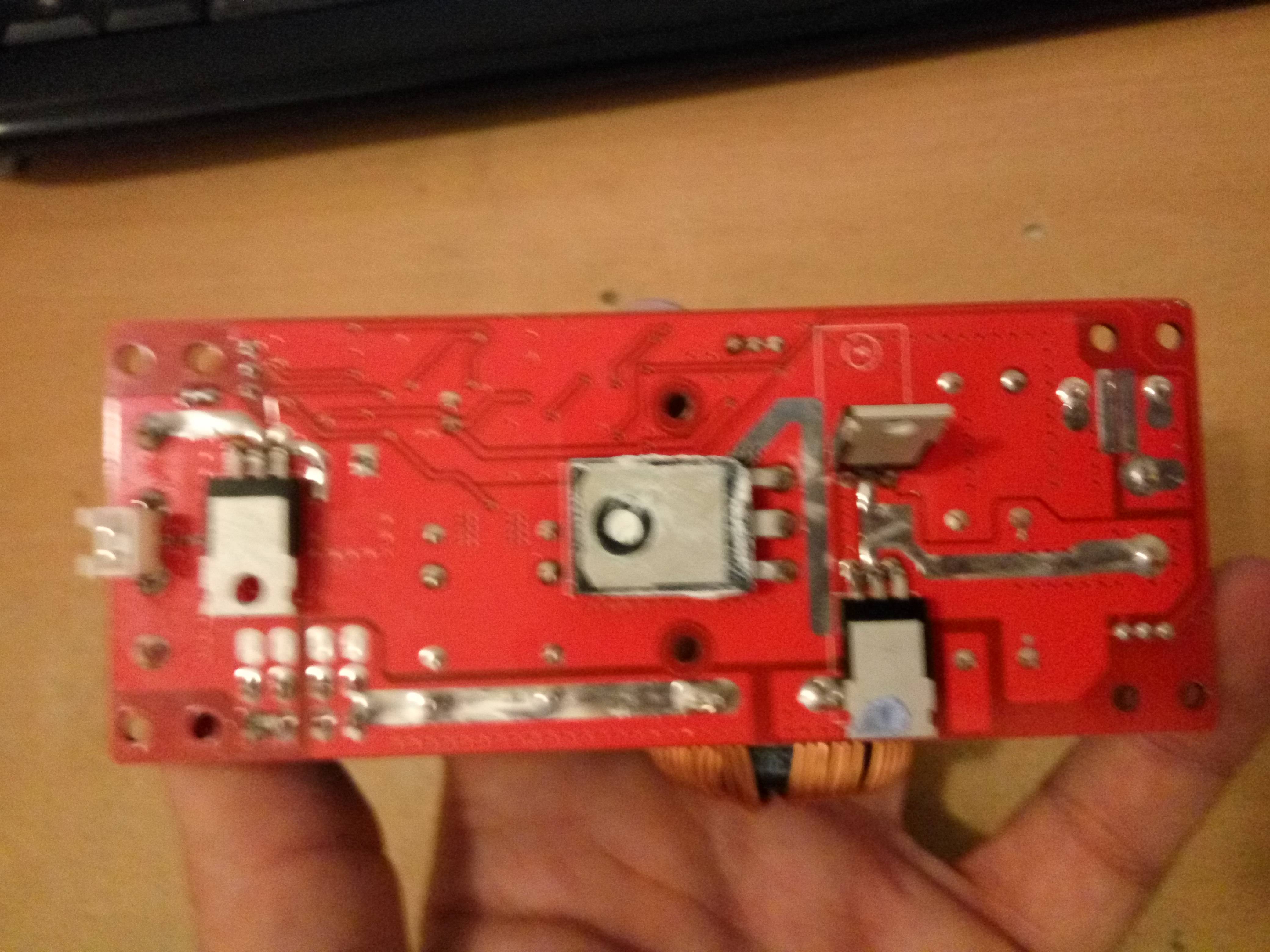
I have 3 small mosfets and 1 big
NnI5AHN.jpg
 
I think it depends on the original wire insulation.

Silicone wire insulation is often very large (thick) compared to the conductor diameter. If your inductor was wound with regular "magnet wire" (with the translucent insulation, often coppercolored), then redoing it with the much larger diameter wire is going to make the transformer huge (and will probably affect it's magnetic properties and/or operation; that part I don't know as much about).

Even teflon insulation is much thicker than the original insulation, but it's generally a lot thinner than silicone would be on the same size conductor.

I'd go with something that has the same or thinner insulation (but will still handle the voltages it will see), as the original.
 
NnI5AHN.jpg


You can have only so many quoted items embedded inside each other so I paired off everything.

I'd have to say no to silicon insulation. It's probably way too thick and you won't get more copper on the core. You would be surprised where you can scrounge transformer wire. Have an old TV with a CRT in it? They all have a degousing coil around the perimeter of the picture tube. Same for old computer monitors that have a picture tube. That coil can be reused. There's probably 100-200 feet of transformer wire there. Have an old washing machine or drier or microwave oven? Same thing...there's large amounts of transformer wire in the motors or magnatron.

I bet 2 of those are mosfets and the other 2 are diodes. These types of devices need hi speed diodes so leave those alone. You'll find that they are back to back diodes.

The larger part in TO-247...probably that's a double diode. Same for the TO-220 part by the JST connector. Look up the part numbers on them. It will be obvious on the data sheets for each part what they are.

Google is your friend...
Let's say you are looking for a data sheet for 4110 on the part. Just search for "4110 datasheet". In my search just now, 5th from the top was a link to infineon who makes the IRFP4110 mosfet and that got me to this PDF.

https://www.infineon.com/dgdl/irfb4110pbf.pdf?fileId=5546d462533600a401535615a9571e0b

Don't worry about all the specs for each part. All you need to do is identify what parts are the mosfets and ignore the others. If this is getting overwhelming for you...and I do understand....especially if electronics isn't your thing...post pictures of each part and I'll help you figure it out. I do this all the time.
 
ElectricGod said:
You can have only so many quoted items embedded inside each other so I paired off everything.

Im not sure i understand this line...


About pcb - big one is mosfet - hy3912 http://boorzia.com/download/HY3912W.pdf

1 alone is also mosfet - nce80h15 https://www.chinahao.com/product/566816589756/

2 small near big one - i guess those are diodes - https://www.onsemi.com/pub/Collateral/MBR2060CT-D.PDF


wire on toroid inductor is 3 x 1.2mm thick. Im not sure where i can find thicker. For example - microwave have often 1mm wire in primary coil...
 
krlenjuska said:
wire on toroid inductor is 3 x 1.2mm thick. Im not sure where i can find thicker. For example - microwave have often 1mm wire in primary coil...
Then as he pointed out in a previous post, you just use multiple strands of that wire in parallel, all wound at the same time.

Meaning, if you unwrap the toroid and find it has, say, 10 feet of wire on it, and you want to almost triple the wire thickness, then cut 30 feet of the 1mm wire in 10 foot sections.

Hold all three in parallel, and connect one set of 3 ends together. (each to the same end of the other two wires).

Then connect the other set of 3 ends together.

Then wrap that wire, just like that, around the toroid, the same way it was wound originally.

Now the wire will be almost 3x thicker, even though it's in 3 "individual" wires, because they are all in parallel.
 
Back
Top