I found a text on their website that seems to descrive the different controller size they have:
(used Babelfish translator Chinese simp to english)
Product introduction and parameter
Product range: The XC846 monolithic integrated circuit makes controller's master control chip
Product classification: Chip version series
Product model: EB812XC-A
Refresh time: 2009-3-8
 Product synopsis:
XC846 monolithic integrated circuit synopsis
1st, the XC846 monolithic integrated circuit designs the production by world-famous semiconductor company Infieon, is the automobile level microprocessor.
2nd, XC846 according to the automobile level's standard design production, the trouble-free service temperature reaches 130°c above, is higher than PIC16F72, CY8C2443A, NEC9234, the R8C series, TMP88F846UG by far and so on monolithic integrated circuit 85°c technical grade designs, enables the controller to be possible in a worse heat, the vibration and under the electromagnetic interference environment works.
3rd, XC846 the monolithic integrated circuit fiach space is 4K, the disposable compilation's program limit is broad, and simultaneously realizes the function are many.
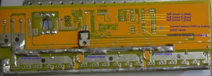
4th, takes controller's core MCU by XC846, may output 6 group independent belt dead area protection 16 PWM, namely enhanced the performance to simplify the periphery component arrangement, the part quantity reduction reduced the controller cost at the same time to enhance the reliability.
5th, XC846 has the field best real-time performance, the operating frequency reaches as high as 26.67 Mhz, handling ability compared to PIC16F72 which, CY8C2443A, NEC9234, the R8C series, TMP88F846UG present industry in uses and so on must be higher than above 52%.
6th, XC846 uses the TSSOP subminiature seal, pin several 38, may provide most IO ports to reach 15 to use in the function expanding, may realize the control, the measuring appliance integration, simplifies the complete bikes to design and to reduce the complete bikes cost.
XC846 plan serial products type:
1st, ordinary series, remote control security lock electrical machinery series
2nd, zero power loss series
3rd, multi-purpose from study series
4th, does not have the Hall series
Technical parameter:
1st, working voltage: DC24V/DC36V/DC48V/DC64V/DC72V
2nd, governor deflection: 0~100%
3rd, working efficiency: ≥84%
4th, current limiting electric current: 6 ≤18A, 9 ≤25A, 12 ≤35A, 18 ≤55A
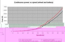
5th, rated power: 6 350W, 9 450W, 12 500W, 18 1000W
6th, fixed power loss: <1.5W
Function characteristic:
1st, time the start noise control, causes the electrical machinery to be able to surpass the static sound start;
2nd, the independent 6 group PWM space vector modulating technology causes the magnetic moment control to be more accurate, brings a better speed change and the braking quality, simultaneously reduced the energy consumption, the continue voyage distance enhanced above 9%;
3rd, zero power loss series control panel: In only lacks two not commonly used function mouths with the ordinary board on as controller's audio frequency output, zero power loss to compare, uses zero power loss pattern, causes the controller in the security condition power loss extremely micro, when control panel when security condition, can deadlock automatically the electrical machinery, causes to rob the vehicle to be unable to carry out;
4th, does not have the Hall series control panel: The phenomenon which uses 1 group independent PWM when in the original independent 6 group PWM foundation to carry on Hall to adjust brings a better speed change and the braking quality increases the starting torque, the reduction start backs up, simultaneously reduced the energy consumption; The continue voyage distance enhances above 9%;
5th, linear EBS gets on the brakes as well as slides in the counter-charging-up voltage as well as the electric current accurate control, guarantees in this process controller's security as well as the control effect, and supports the EBS linear brake crank;
6th, the formidable hardware monitoring protection module, guaranteed that the electrical machinery movement is reliable, and convenient breakdown judgment;
7th, the complete function according to the modular design, the user may through the hardware wiring or the serial port communication disposition functional module and the system parameters;
8th, the intelligence from the study function, may outputs according to the phase line connection and the electrical machinery phase angle adjustment controller;
9th, this series control panel realizes the control by the unique programming, causes the electric car driving system work in the optimum condition, thus enhances the product the reliability and the service life;
10th, the software, the hardware simultaneously have the start short circuit protection, the movement short circuit protection, to stop up transfer the protection, the undervoltage protection, on the electricity against speeding car protection, to move against speeding car protection, the soft start, the brakes automatic power failure, the high/low level braking, the cruise, 1:1 boost, three speeds, three speeds to instruct that the high/low level security may choose, functions and so on back-draft, failure indication, pronunciation warning, reliable carries on the protection to the electrical machinery and the battery; The control panel high performance, the reliability is high; The control panel has the ABS electron brake system, the counter-charge system, the driving circuit observation system, the function port, flexible, the convenient user carries on the production;