• Howdy! we're looking for donations to finish custom knowledgebase software for this forum. Please see our Funding drive thread

24s BestechPower BMS Thread

I'm joining the fun with the little 14s version of these. I've begun reverse engineering and hope to figure out how most of it works.

To test any FET to see if it is on or off, measure the voltage across the two outside legs. Zero volts = off, over 5v = on (but most FETs want at least 8v to be fully on).

It seems it doesn't like turning on against a load when you switch the thermal breaker. I'm planning on revising the circuit on mine so it can be used as a precharge/main contactor.
 
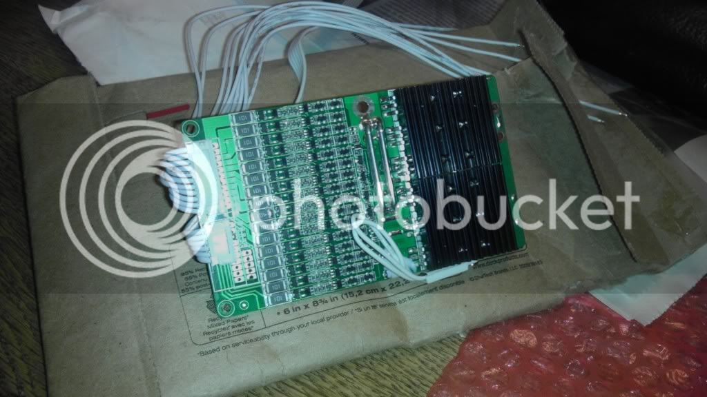
Here is the 16S d167 that I bought from dnmun and then modified to work for 12s.

IMAG0844_zpsc2cecf91.jpg


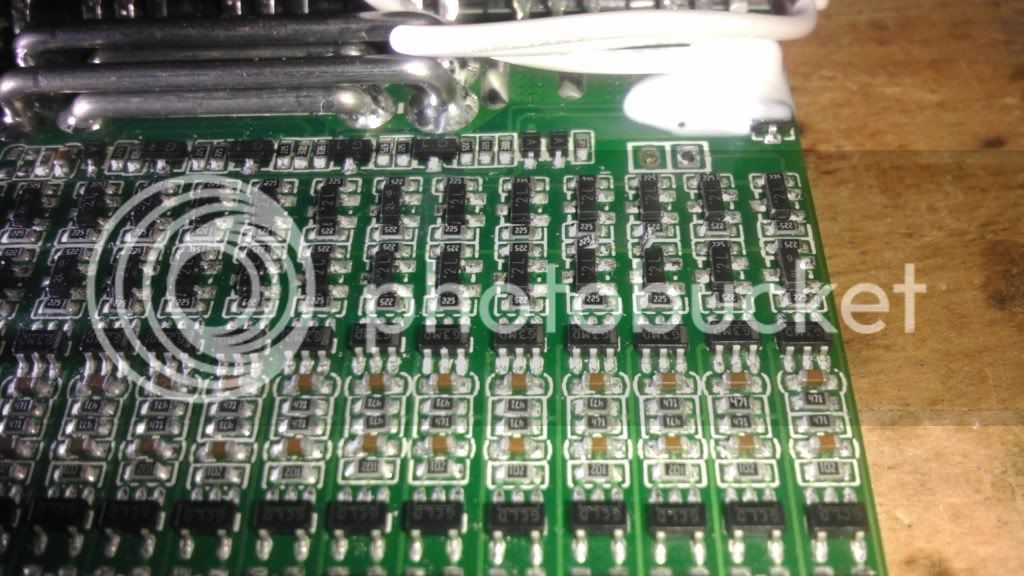
I followed dnmun's advice to just lift the small resistor out of the way so it could be easily replaced.

IMAG0854_zps78ee587e.jpg


IMAG0855_zps35930cc1.jpg


Hopefully, I'll be able to test it soon to see if charging works OK and it can handle high current spikes.
 
That should work. Interesting that board uses a completely different setup than the one I'm playing with.
The resistors lifted are in the signal chain for HVC and LVC.
 
i think that row is the LVC signal. i told him to wait on opening the top row where the HVC signal line is in case it will work without hacking the HVC signal. if it won't charge he can lift that resistor then to see if it starts charging after that.
 
dnmun said:
i think that row is the LVC signal. i told him to wait on opening the top row where the HVC signal line is in case it will work without hacking the HVC signal. if it won't charge he can lift that resistor then to see if it starts charging after that.

There's a good chance it will work without lifting them since the voltage detector chips on the unused channels won't have any power and won't activate. The signal chain could be looking for either active high or active low, so hard to say for sure without testing.
 
i had never even thought to not do some hack. if i had tested it at 20S without the hack of removing the resistor i bet it would have worked. i just decided to lift that resistor, it worked after that, and that was proof, but it was a false assumption.

my logic was that the next channel up would be at zero volts because there is no cell, so the comparator would turn on the mosfet and short the voltage of that channel to the signal line. but the comparator has no power, so it would not send a signal to the transistor so it is null.

there is no voltage from the battery to the channel to deliver current to the signal wire anyway.

now i gotta test this. but i totally agree with what richard said now.

this was not possible with the ping signalab BMS. you had to jumper over the optos on those BMSs.
 
Make sure it works first. No returns on potted boards.
Potting should be fine. It prevents all kinds of bad things from happening. It also generally prevents any kind of repair. Conformal coating is another option. This makes repairs somewhat possible.
 
fechter said:
Make sure it works first. No returns on potted boards.
Potting should be fine. It prevents all kinds of bad things from happening. It also generally prevents any kind of repair. Conformal coating is another option. This makes repairs somewhat possible.

I purchased extra boards. I will post my results.
 
you could even seal the sense wire plug if you used silicone grease on the pins. put contact adhesive around the wires in the back of the plug so it would be sealed there between the wire and space for the pin clip,and cover the exposed sides of the pins on the outside of the socket where it is soldered to the pcb. the conformal coating could work there too. on several of the BMSs they use conformal coatings contact adhesive or epoxy coating over the circuitry to keep them from shorting. on the backside with shellac and over the shunt resistors too.

these D131 do not have any of that yet. last thing i would do since i am always tinkering with them, but if it is gonna be really wet it could help.
 
dnmun said:
you could even seal the sense wire plug if you used silicone grease on the pins. put contact adhesive around the wires in the back of the plug so it would be sealed there between the wire and space for the pin clip,and cover the exposed sides of the pins on the outside of the socket where it is soldered to the pcb. the conformal coating could work there too. on several of the BMSs they use conformal coatings contact adhesive or epoxy coating over the circuitry to keep them from shorting. on the backside with shellac and over the shunt resistors too.

these D131 do not have any of that yet. last thing i would do since i am always tinkering with them, but if it is gonna be really wet it could help.

I planned on sealing up to the sense wire back side connection & using a dielectric grease on the connector.

What conformal coatings are being used these days?
 
no idea. but on these new headway BMSs they use some black potting liquid in some places, painted on, and then over a broad area above the balancing resistors they used a clear less viscous type so it spread out thinner. does not cover the entire pcb, just the comparators and transistors and little resistors on the signal lines and transistors.

there is none on the mosfets or the sense wire plug. no dielectric grease either.
 
finally got a chance to test the hack of the 16S D167 lipo BMS down to 10S to see if it would work without lifting the resistor but just populating the BMS with sense wires up to the length of the battery and leaving the other BMS channels unconnected even though they are populated with the circuitry for the upper channels..

i just soldered on a 10S section of sense wire and tested the gate voltages of the two banks of mosfets and they are all turned on at 7.7V.

so dufous, i was so convinced i had to lift that resistor, i should laugh. duh. never tested it, totally false assumption.
 
dnmun said:
joshuahandrich did that on his scooter thread. i forgot where it is but he may pipe up yet.

Run your dc-dc converter off of the discharge output of the bms. use a 12v automotive relay which is normally open, and connect it to the 12v system of the bike from the output of the dc-dc converter. You can then connect this relay to close the e-brake line, connect your ignition wire to battery +, or to open the signal or 5v line for the throttle. this way, whenever the bms cuts out, your power will be cut.

If you wish to disconnect the controller from the battery completely, you could use a large high voltage relay powered by the 12v line.
 
zlagger said:
Any luck with bypassing the output circuit and just breaking the throttle signal on these?

The dc-dc and large relay approach works fine and is good for high powered setups.

The other way to do it is to bypass the FETs on the BMS and use the gate drive on the discharge FETs to pull down the throttle (through a diode). I'm not sure if the chips on the BMS have enough current rating to pull down the throttle line directly (I might try testing this). If not, a simple single transistor can boost this. It's pretty easy to make a connection to the gate leg on the FET.

You could also beef up the shunt on the BMS so it can handle the full desired current (this may require a large, off-board shunt). While still bypassing the FETs for discharge, but going through the shunt, you could keep the overcurrent and short circuit protection. The G2 suffix chips will trigger overcurrent shutdown when there is over 100mV across the shunt, so you can calculate the cutoff current. I think most of the other versions are probably about the same.
 
I tested with my D126 board and the gate pull down is not strong enough to pull down a 5v throttle signal through a 1k resistor. By adding a small PNP transistor, it pulls down to 1v, which would be fine for most setups.
 
I have a couple of 0v puffed cells because I didn't realize I left the bms connected when I packed everything away for the winter. Is it possible to just run this unit with 23s. That way I do not need to purchase more batteries that are not of the same age, and I also give my 4110 fet controller a little more voltage headroom. Doing this, I would lose less than 4% of my batter capacity and top speed, and I never use all of my charge and have never tested the top speed anyways.
I will obviously be more diligent with the pack and the bms in the future.
Apparently it only draws power from cell one. I will most likely incorporate a switch to break the ground connection of cell one to disable the bms easily when it will not be used for long periods of time without disassembling the bike.
 
which ones are 0V? did you try to charge them back up slowly?

that was kinda fast since you were using that BMS recently.

the D131 takes power off top of #3.

i thought that one had a switch to turn it off or did i not include one?

it will run on 23S without modification. just adjust the charger down and leave #24 empty.
 
Back
Top