24s BestechPower BMS Thread

Yes, it makes sense, and it is basically what I was planning other than completely shorting out battery channel one, though that makes sense.

I am positive that Q1 is shorted and none of the others are. It has 0ohms of resistance measured in either direction whereas none of the others exhibit any thing but an open circuit between any of the legs in any direction. Trust me, I know what I'm talking about.
 
i must admit i was too lazy to re-read the whole thread, so i can't be sure it wasn't mentioned before.
today i installed my lipo 12s hcx-d131 bms and started charging a somehow dis-balanced 12s pack. it was around 90mv from lowest to highest cell.
during charge i disconnected the balance wires and expected the charge to stop. but nothing happened. that's a very bad thing as there is no way to tell from the outside that all balance wires are still connected. so if some wire is loose and it over charges (above 4.28v hvc) in my case the bms is not aware of that situation and therefore doesn't stop the charge.
is this correct behaviour?
 
check the charging mosfets to see if they are still turned on. if they are turned off at the gate and still conducting then they are shorted. you can use the diode tester on your DVM to test the mosfets.
 
dnmun said:
check the charging mosfets to see if they are still turned on. if they are turned off at the gate and still conducting then they are shorted. you can use the diode tester on your DVM to test the mosfets.
so you say that it SHOULD turn off? i connected battery first, and balance connector second. correct?
 
i know it's the 24s thread. and i didn't check before. seems the 12s has only 84mA balance current. anyone knows why? how can i have 144mA as with the 24s? balancing a 20Ah pack takes ages with 144mA but with 84mA it's much worse.
at least this is what the printed manual says. it's WEIRD. the homepage says 168mA. and the manual of my 24s LiFePo4 bms says 144mA. what does this depend on? i may disconnect a balance wire and measure myself.
 
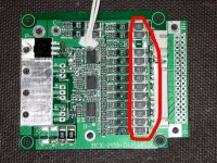
Look for the shunt resistors on the board. V/R=I, so if you have 100 ohm resistors @ 4.2v, you get 42mA.

On some boards there are unpopulated spots on the underside where you could add more resistors. Another 100 ohm in parallel would double the current. The tiny little FETs that switch the resistors on are typically rated for a maximum of 250mA.

Here's what they look like on a D126 board:
Shunt Resistors.jpg
 
the D131 has four 100 ohms 2512s in parallel and at the balancing voltage of 4.2V that is 168mA. any current over that is going into the cell.
 

Attachments

  • DSC01606.JPG
    DSC01606.JPG
    86.2 KB · Views: 1,831
  • DSC01635.JPG
    DSC01635.JPG
    74.9 KB · Views: 1,831
there are ALL resistors present at the board. and all of them are 100ohm ones. so i guess the manual is wrong.

still i don't know how to measure the bleeding current. if i cut one balance wire and measure the current running from the battery balance wire to the bms it shows no current at all. any other way to measure it?

now that i fully charged the battery i must drain it again. i connected a heater to the bms and it draws some 1.5A. will take some time to discharge, but that's fine. while discharging i disconnected once again one balance wire. i expected the bms to stop the discharge immediately as one cell was below lvc of 3v. but guess what: nothing happened :(

i will take some time and reread the whole thread to see which one are the charging mosfets and which one are for discharging and will measure them as dnmun said. hope i will have an answer then.

edit: with the diode tester i measured the forward bios of the mosfets:

454mV for the 5x charging mosfets
425mV for the 15x discharging mosfets
open circuit when probes are reversed. so they not seem to be shorted
 
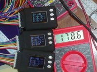
you measure the balancing current in the charging leads. you have to use the 10A scale/spot on your DVM since the current during the bulk charge phase is too high for the 200mA scale. i was able to switch to the 200mA scale for the photo after the pack had reached full voltage and charge current was down to under 200mA.

the mosfets are functional if the body diode is still present.
 
dnmun said:
you measure the balancing current in the charging leads. you have to use the 10A scale/spot on your DVM since the current during the bulk charge phase is too high for the 200mA scale. i was able to switch to the 200mA scale for the photo after the pack had reached full voltage and charge current was down to under 200mA.

the mosfets are functional if the body diode is still present.

it's not the balancing current i'm interested in, but the bleeding current. sorry for not making that clear. how would i measure that?
and why is it that charging/discharging doesn't stop when i disconnect a balance wire?
 
the balancing current is the "bleeding" current.

the balancing current is the current that flows around the cell when the cell reaches the balance voltage and the shunt transistor turns on.
 
Just measure the voltage across the resistors then calculate the current. Measuring directly would be difficult.

If you used a constant current charger set to less than 168mA or whatever the shunts carry, you should be able to force balance on all the cells over time without hitting the HVC.
 
thanks fechter. that's a good way to check it. i'll try later.
i now still do a discharge at 1.5A, so it may need some more hours to reach LVC. gate voltage of the discharge mosfets is 8v. is this ok?
still if i disconnect a balance wire NOTHING HAPPENS - discharge goes on as if nothing happened. what's wrong here?
 
which balance wire did you remove? the output mosfets are not hot from being shorted? but you are only discharging 1.5A so maybe they don't get hot with so little power.

if it does not turn off then i would guess one of the output mosfets is shorted.
 
dnmun said:
which balance wire did you remove? the output mosfets are not hot from being shorted? but you are only discharging 1.5A so maybe they don't get hot with so little power.

if it does not turn off then i would guess one of the output mosfets is shorted.

balance wire removed was from cell 7 and cell 12. don't know if that matters? i hope to work for all 12 cells.
none of the mosfets are only a little over ambient. they are all cool. i measured all of them with balance wires removed (as you wrote some posts last year) and the all show mOhm as posted already. ~400mOhm in one direction and open circuit in the other direction. anything else i can check?
i will now discharge and see what happens when more cells fall below 3.0V.
 
8 volts on the gate is typical. A little lower than I'd like, but enough to fully turn on the FETs.

It's possible that with a balance wire removed, the voltage seen by the BMS is still in the OK range due to the divider resistors in the circuit. You might try attaching a 1.5v battery to a disconnected balance wire to simulate a cell going to 1.5v. This should make the discharge FETs turn off.
 
i measured 4.8(3.38V/cell)-5.2(3.65V/cell)V on this lifepo4 D131 just now.

5.2V for 3x3.65V for the circuit voltage, so maybe 8V for 3x4.2V on the lipo is to be expected. i thought i had seen higher voltage before but now that lipo pack with the D131 is apart again so no way to tell.
 
fechter said:
8 volts on the gate is typical. A little lower than I'd like, but enough to fully turn on the FETs.

It's possible that with a balance wire removed, the voltage seen by the BMS is still in the OK range due to the divider resistors in the circuit. You might try attaching a 1.5v battery to a disconnected balance wire to simulate a cell going to 1.5v. This should make the discharge FETs turn off.

i discharged for almost 7h now. watched the attached cellogs for the last 20min as voltage passed the 3.5v mark. it went down quite fast and i disconnected the balance wire at 3.3v and the discharge STOPPED instantly. i reconnected it but nothing happened. i had to disconnect the main wires to restart discharge.

watch it for some more minutes, the one cell hit 2.99v and BANG the discharge stopped as expected.
so i can tell this thing is working. :) i must say i'm REALLY impressed.

now i have to recharge it and overcharge one cell to see if it stops at 4.25v.

so to repeat: if a balance wire disconnects at let's say 3.5v nothing happens. it will stop if disconntected at 3.2v. but how would the bms know of the low cell if the cell is not connected to the bms anymore? i guess this is a safety risk! i'll investigate further.
 
there is no risk. it will shut off at HVC just like it should. i have pushed the lipo D131 to HVC several times and never had it fail to shut down.

i have discharged to LVC about a dozen times on the both the 24S lipo and the 24S lifepo4 and both shut off on the specific LVC. never failed.

if you had measured the voltage on the #7 sense wire pins on the BMS when you removed it then we would have some idea of what happened. but if you removed the one from the top cell i would expect it continue discharging.

i built this lifepo4 pack to 22S and it functions normally without 23 and 24.
 
dnmun said:
there is no risk. it will shut off at HVC just like it should. i have pushed the lipo D131 to HVC several times and never had it fail to shut down.

i have discharged to LVC about a dozen times on the both the 24S lipo and the 24S lifepo4 and both shut off on the specific LVC. never failed.

sorry that i have to disagree, and i'd be more then happy if you prove me wrong.

following situation: all cells are at a fine state (somewhere between 3.5v and 4.0v). one or more of the balance wires get lose, fall off, what ever. they are not connected anymore.
the bms will work WITHOUT letting you know that there's something wrong. it will charge and it will discharge just fine. so if you are not lucky and one of those cells is in no good shape it may discharge way beyond 3.0v while the rest is fine at 3.5v still.

this IS A RISK. same situation may happen when charging.

please try that: disconnect some cells in the middle and try it. i even disconnected the first 8 cell plug and only had the upper 4 cells connected. worked just fine :(

sure, you may argue that it's very unlikely for a balance wire to get lose. but wires GET LOSE!
 
dnmun said:
if you had measured the voltage on the #7 sense wire pins on the BMS when you removed it then we would have some idea of what happened. but if you removed the one from the top cell i would expect it continue discharging.
it was cell #7 that i disconnected, and did all the tests with.
 
when you do it again will you measure the voltage on the pins of the sense wire plug where the plug is soldered into the BMS? you can measure the voltage between the solder bumps on the back side of the pcb.

yes i have had loose sense wires but the BMS would not function then so that was why i asked you to measure the voltage on the pins.

you may have your own agenda to argue that they are defective but i have not seen that even when i had similar presentations.
 
dnmun said:
when you do it again will you measure the voltage on the pins of the sense wire plug where the plug is soldered into the BMS? you can measure the voltage between the solder bumps on the back side of the pcb.

yes i have had loose sense wires but the BMS would not function then so that was why i asked you to measure the voltage on the pins.

you may have your own agenda to argue that they are defective but i have not seen that even when i had similar presentations.
good to hear. as i said: i'd like to be proven wrong. i don't want this to work as i observed it. i want to have a bms that is as safe as can be. so maybe i'm just doing something wrong. i'll try to find out.
so if you ask me to measure the voltage, you want me to measure the voltage between one solder pad of the balance plug to the next one - especially the voltage of the now disconnected cell. correct? i could do it like you did and solder connectors for cellogs to it. would make things easier.
at the moment i have the cellogs connected to the battery directly with a parallel harness - so they always show cell's voltage and not the voltage the bms sees.
 
Back
Top