24s BestechPower BMS Thread

So what type of oem is buying thousands of 18 and 20s BMS units? Just curious what their 'real' target customer is since of course it's not a few dozen of us building custom e bike packs. Anyone have an idea?
 
most of the major shipments for these guys are to local battery makers in china or japan. i bet most of them they make are the ones for bottle batteries, made to fit the form of the case, these big 24S type builds are a one off in terms of the overall volume. nobody in the real world can sell a bike with the type of battery a 24S makes.

most will be the 10S lithium ion, 13S li ion, in terms of volume imo. i wonder how much of the chinese market is using 100V lipo batteries now? i would call this stuff experimental. hi risk, so highly regulated in the real world.
 
Ya, up to 13 or 14S makes sense for most commercial e-bikes I've seen. In the USA at least, I don't know of any OEM bikes with voltages above the low 50s. It's just curious that these chinese electronics/engineering companies bother to make 24S BMS's if there's no real market for them, but it's good for us that they do I suppose.

I think I'm going to pull the trigger and order two of the D166-18S units from them. Hopefully at least one of them will work alright, if so I think it's worth the cost. If they're both OK I may sell the other one on the forum or something. Don't really need two but what the heck, shipping is 50% the cost of the module and it sounds like the odds of getting a dud might be higher than in ideal circumstances.
 
i asked henry to consider using the hong kong post to cut down on shipping.

before you order a new one why not go through what happened to yours. did you test the mosfets or is the BMS still on the battery so you can test the gate voltages?

i just got the 4 milliohm shunts for the over current hack, but waiting on hobbyking for my batteries.

the bottle batteries they can make 10S of li ion and call it a 36V battery so that is why there is a strong market for the specialized pcbs that go into the cans.

also 13S is very common since 13S of li ion can be called 48V which is what they do.

the old format of 4S,8S,12S,16S following on the old lead acid increments doesn't mean anything anymore.

the 24S is the result of the next progression up from 48 and 60V nominal in lifepo4. so they had a 24S BMS pcb and all they had to do it add the lipo comparators instesd of the lifepo4 comparators and it works on lipo.

i will look at the D166 design too.

edit> that design seems to have only the one 100 ohm shunt resistor so the balance current is only 42mA. is there a resistor on each channel on the underside of that pcb?

the D131 and D138 has 4 of the 200 ohm shunt resistors and the equivalent resistance is only 25 ohms so the shunt balancing current is 168mA or 4 times as much as the D166 and has a few more mosfets too. how much is the D166? the D131 was $58 for 24S lipo. in fact the D131 and 138 have the highest balancing current of all of them.

ps: the 26S lifepo4 BMS is there because they could do it i think. they just stretched the 24S pcb a little bit longer to make it 26S. there is no 26S lipo but i bet you could get them to adapt that one to lipo by swapping in the lipo comparators.
 
I don't have any BMS, my old pack was 18S LiPo using 'manual' BMS meaning careful monitoring and balance charging, but somehow I had a current drain. I still need to find it actually, think it might have been some cell monitors I was using from hobby king that pulled current even though the ground on the multi-pin connectors was switched off. Could also be something in my controller. I left the controller turned off, but the main breaker to my battery turned on and when I came back a couple weeks later battery was at 3 volts (total, not per cell). I did the high voltage mod on the controller by changing resister values for the reference voltages (it's an infineon 25A from GrinCyclery), so I need to see if somehow something in the controller is allowing a slow bleed of the pack.

Regardless, I think these BMS's look like they're worth a try. The other option is Methtek's LVC/HVC and parallel board system, which I like and I know works well from what others have reported, but this is cheaper and if it works the balance feature is nice.
 
i recommend going to the D131 for the balancing especially since you have some cells that have been to the bottom already. the lifepo4 cells seem to have a high internal drain down rate after going to low low voltage and i expect the same from the lipo. so for that reason i think the higher balance current is best.

also since the cells have been abused it is essential to know when they finally short out. when bulk charging the presence of one low cell can allow the other cells to be forced into over charge so having the BMS to flag the failure will help provide the input to know when to repair the pack. jmho

when the pack fails to charge because of a dead cell then it gives you the clue to fix it. plus the presence of the BMS will prevent the pack from over discharging by accident on the controller. this is really common. alanB found that the newer controllers have drain down resistors on the input caps so that is how your pack was drained while the controller circuit current was turned off.

so the higher shunt balancing current is the most attractive part of these big ones. even though lipo is very good about staying close together.

the 25ohms of the D131 is about 2 1/2 times the shunt resistor in the icharger BMS. the icharger has 9.4ohm equivalent resistance so it will balance at 447mA and the D131 will balance at 168mA rates.
 
@dnmun: do you have any idea which resistor(s) to change to set the balance voltage? atm it's set to 3.6V for my lifepo4 system. but as cells start to drift heavily as soon as they move above 3.45V (some stay there for longer, some climb to 3.75V), i'd like to lower balance voltage to 3.5V. so i would set end voltage to 3.65V per cell, so every cell will reach 3.5V minimum and that way can be bleeded down to 3.5V making the pack nicely balanced.
 
you would reduce the charger voltage if you wanna lower the balancing voltage but you should charge up to the 3.65v level though in order to fully charge the cells.

a little over 59 up to 60 is ok for the 16S of lifepo4. the extra voltage above the 58.4V level forces the cells which are lower to fill.
 
dnmun said:
you would reduce the charger voltage if you wanna lower the balancing voltage but you should charge up to the 3.65v level though in order to fully charge the cells.
a little over 59 up to 60 is ok for the 16S of lifepo4. the extra voltage above the 58.4V level forces the cells which are lower to fill.
lowering the summed up end voltage would NOT change the voltage per cell at which balancing would start. as i understand it: a cell reaches 3.6V, and the bleeding resistors start reducing the voltage of this particular cell by burning this over voltage.
if i set the charger to 87.6V which equals 3.65V/cell, some cells will still have 3.55V whereas some will have 3.75V. those with 3.75V will be pulled down to 3.6V, but whose with 3.55V will stay there. so after balancing you will still have a un-balance of at least 50mV.
if i now raise the end voltage to 90V (which equals to 60V for 16s or 3.75V/cell), than some cells will reach maybe 3.9V which is the ultimate for a lifepo4 regarding life span. i don't want to charge that high. i prefer charging to 3.7V max and then balance to 3.5V. as those bms are said to be adjustable (by factory though) there must be (maybe) a resistor who is responsible for the balance voltage. i don't think that you loose many mAh, as a single push on the throttle brings voltage down from 87V to 83V, which is a decline of 150mV/cell.
 
that is not how they work. you cannot change the setting in the comparator so the voltage where the shunt transistor turns on is permanently fixed.

the reason for charging to full voltage is so that the low cells can charge up also. for 24S you should have a minimum of the 87.6V and i recommend adding a little more to force the low cells to charge up also.
 
dnmun said:
that is not how they work. you cannot change the setting in the comparator so the voltage where the shunt transistor turns on is permanently fixed.
the reason for charging to full voltage is so that the low cells can charge up also. for 24S you should have a minimum of the 87.6V and i recommend adding a little more to force the low cells to charge up also.
ah ok. just checked again. the balance voltage is NOT adjustable. it's a fixed voltage. that's bad :(
but as i stated in my post: if i raise the voltage, some cells may overcharge. these cells will be protected by the bms, as the bms shuts off as soon as one cell reaches 3.9V. but i would prefer no cell reaching this voltage at all. or do you call 3.9V a still safe voltage for lifepo4?
 
Ok here is what I have.

BMS disconnected from anything.

The 5 charging mosfets I measure :

red probe middle black probe right 004 and beeeeeep on multi meter
and same result when reverse the black and red probe.

All other mosfets :
black probe middle red probe right 390
if I reverse red and black I measure nothing.

Charging mosfets dead ? Is it possible to hear them ticking when I charge a battery ?
 
Bazaki said:
Ok here is what I have.

BMS disconnected from anything.

The 5 charging mosfets I measure :

red probe middle black probe right 004 and beeeeeep on multi meter
and same result when reverse the black and red probe.

All other mosfets :
black probe middle red probe right 390
if I reverse red and black I measure nothing.

Charging mosfets dead ? Is it possible to hear them ticking when I charge a battery ?

yes, if the diode tester reads 0004V when you put the red probe on the drain and the black probe on the source then the mosfet is shorted.

the 390mV is the forward bias of those other output mosfets, and when you reverse the probes the circuit is open so you get the ---- on the meter. that is the reversed body diode.

not sure how you killed the charging mosfets though. they would have been damaged when current flowed through the body diode and cause the mosfets to overheat and blow open.

did you talk to henry about replacing it? those mosfets can be replaced too and the BMS should still work.

you can plug the sense wire plug back in and measure the gate voltage on the end where all those pins are lined up between top and bottom.

the pins are in groups of 2 at a time. each two pins are tied together on each end where they are soldered down.

counting from the right, the second to last group of two pins is the gate voltage of the charging mosfets, and the third group of two pins is the gate voltage of the output mosfets. there is the D4 printed just above the pins with the gate signal for the output mosfets
 
dnmun said:
yes, 3.9V is not harmful, it is not as big a problem as under charging the cells because that allows the low ones to fall farther outa balance each cycle.
ok. good to know. then i'm fine :) just need a solution to cool those f***ing hot resistors. the board below them gets 100°C+. but i guess this is what it's designed for *ggg*
 
on the icharger where there is even more shunt current and more heat, they cut slots in the pcb on each side of the resistors so air can circulate around them. the old ping v1 BMS had big 22 ohm 5W power resistors and they would get hot too. they were regular leaded resistors standing above the pcb. the old headway BMS 20 ohm shunt resistors would get hot too. that's what they all do for a living. just get hot.
 
dnmun said:
Bazaki said:
Ok here is what I have.

BMS disconnected from anything.

The 5 charging mosfets I measure :

red probe middle black probe right 004 and beeeeeep on multi meter
and same result when reverse the black and red probe.

All other mosfets :
black probe middle red probe right 390
if I reverse red and black I measure nothing.

Charging mosfets dead ? Is it possible to hear them ticking when I charge a battery ?

yes, if the diode tester reads 0004V when you put the red probe on the drain and the black probe on the source then the mosfet is shorted.

the 390mV is the forward bias of those other output mosfets, and when you reverse the probes the circuit is open so you get the ---- on the meter. that is the reversed body diode.

not sure how you killed the charging mosfets though. they would have been damaged when current flowed through the body diode and cause the mosfets to overheat and blow open.

did you talk to henry about replacing it? those mosfets can be replaced too and the BMS should still work.

you can plug the sense wire plug back in and measure the gate voltage on the end where all those pins are lined up between top and bottom.

the pins are in groups of 2 at a time. each two pins are tied together on each end where they are soldered down.

counting from the right, the second to last group of two pins is the gate voltage of the charging mosfets, and the third group of two pins is the gate voltage of the output mosfets. there is the D4 printed just above the pins with the gate signal for the output mosfets

Hmm not sure where I need to measure, I took a picture and here I found the D4 printed.
imag1137y.jpg
 
those two pins in the white square below the D4 are the pins that have the gate voltage for the output mosfets.

the two pins just to the right are the gate voltage for the charging mosfet.

you can put the black voltmeter probe on the B- or on the shunt wires and use the red probe to measure the gate voltage on each set of mosfets. you should always do this when you set up the battery to make sure it is functioning before plugging the charger in.

not sure how you wired it up, but if current flowed through the mosfets with the source leg more positive than the drain then the mosfet could not turn it off because it is forward biased as a diode and that is what caused the heat to damage it,imo. or my guess anyway. the mosfets are 4310 on my little D126 so i suspect they are the same on yours and that should be BVdss of 100V. so your charger should not break them.
 
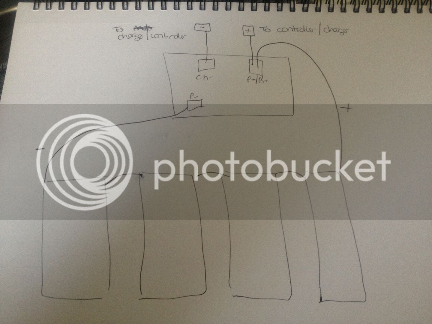
the negative terminal of the battery connects to the B- spot on the BMS.

there is no P+ or B+ spot on the BMS. the power, the red B+ wire connects directly to the red B+ wire on the controller.

the controller circuit current is connect to them by a switch. except some controller now have a drain down resistor on the input caps.
 
the manual is quite clear i guess:

bms_connection.JPG


the wire from battery+ is split. one end goes to the controller, one end goes to the charger.
battery- is directly connected to the bms.
as well as each negative of the controller and of the charger has it's own solder pad on the bms.
so to repeat: NO positive wire is connected to the bms. and each negative one has it's own solder pad. one for the battery. one for the charger, one for the controller. pretty straight forward :)
 
Back
Top