5000w Hub Motor Phase Wire Quick Disconnect System Ideas

dragon

1 W
Joined
Feb 2, 2023
Messages
58
Location
Calgary, AB
Please bear with another question from a newbie:
I have on order a qs motor 17x3.5" 5000w hub motor & I want to put in-line quick disconnects to facilitate future rear tire changes & make towing with a motorcycle tow dolly electrically safer.

Which connectors would best be able to handle the phase wire connections of a 5000w motor? My controller will be a ND72680.

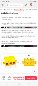
I feel more comfortable with mechanical crimp connections than soldered ones so originally I was planning to crimp heavy duty ring terminals & use one of those yellow junction boxes or encase the terminals in a tiny aluminum box/case.

Alternatively would mt60 connectors be able to handle the current? How about XT90’s or XT150’s

Another crazy thought I had was to use a 3-pole circuit breaker.

Any suggestions from the electrical gurus on here?
 
The ND72680 makes up to 680 phase amps. None of the RC-plugs will do the job. I would use something like half of a motor terminal board with cable lugs and screws.
 
I beg to disagree, Xt150 will work as long as they’re in free air and the phase wires are thick enough, but i would rather use the larger 8mm gold bullet connectors like the ones from hxt or castle creations. On my efoil where the connectors get no cooling these work great and are some steps better than the xt150s.

It makes a huge difference if you put the wires in free air or bundle them together in a cable sleeve.

It is also better if the three connections are offset by 2”/5cm so that they’re not bundled side by side.
 
Last edited:
Personally I'd use crimp-on ring terminals and bolt them together. If you use a terminal block, don't use the crappy "yellow" ones (color doesn't matter). We've seen problems with the threads stripping before sufficient tightening is achieved, and then the resistance of the connection may be too high, and it may heat the connection and melt the block and the wire insulation, etc.

Alternately, you can use the Anderson SB series of connectors--they make them for very high currents, though they are quite large and bulky for the current, they are actually able to handle the rated current continuously under whatever conditions you wish to use them in (as long as those are within the bounds of the spec sheet).
 
Or something like this, but I do not know how small they are and if they fit your phase wires
 

Attachments

  • Screenshot_20230223_212149_AliExpress.jpg
    Screenshot_20230223_212149_AliExpress.jpg
    524.3 KB · Views: 5
  • Screenshot_20230223_211227_AliExpress.jpg
    Screenshot_20230223_211227_AliExpress.jpg
    707.1 KB · Views: 5
The voltage rating of the bolt-on connection isn't really relevant--there is no voltage across the actual connection if it's correctly connected (if it isn't, voltage will be the least of your worries ;) ), and the gap between bolts is large enough for probably a few hundred volts. ;)

The diameter of the bolts relative to the wire size also isn't really relevant, directly. What matters is that the bolt, washers, and nut can provide sufficient tension, evenly over the entire ring terminal's surface area, to clamp the rings together for minimum resistance. Generally the bolt shaft should be the same size as the hole in the ring terminal, and the bolt head and washers should match the outer diameter of the ring. If the head / nut are too small, very stiff / thick / hard washers must be used to help spread the tension evenly across the whole ring surface. (the rings themselves will be too soft to do this on their own)

The ring terminals themselves should be sized to carry the current required--not just for the wire gauge crimp size. If they are too small, they will have insufficient contact area and too high a resistance, and will heat up (more the higher current).


It probably is a good idea to not use whatever "busbars" they provide, and instead directly bolt the controller and motor rings together--the connection will be lower resistance.
So if I'm understanding correctly, I could use any of my options provided I size the ring terminals correctly to the threaded posts.
 
So if I'm understanding correctly, I could use any of my options provided I size the ring terminals correctly to the threaded posts.
If you size the ring terminals correctly for the current required, and then size the posts (bolts, nuts, washers) correclty for the ring terminals. ;)


Well, I don't think the three pole circuit breaker would be much help. ;)
 
Back
Top