72v 1500W 40A Hua Tong CA08 XM06AD_P04.1 controller

Gordo said:
It has been tested to destruction. Read the thread.

Oh sure, I've been following the thread. Has anyone re-programmed one, devised a USB -flash system? Is it possible??

I don't mind finding out, if somebody could tell me how.......

....should I write to their factory?

Thanks.
 
I read that people have been able to program the standard infineon, but with this controller, you need to know both the cpu and the software
 
Gordo said:
I read that people have been able to program the standard infineon, but with this controller, you need to know both the cpu and the software

Ok, thanks Gordo, does anyone here know how to go about this? Speak to the sellers, do an online search for the manufacturer etc etc?

I would be happy to do the work, any suggestions would be gratefully received.

Thanks and good luck.
 
We have talked to the sellers' and they say it can not be programmed. We know this is not true. You will have to search ES for threads on programming and then determine which CPU is in your controller. I have no experience with programming controllers, only with JTAGing Sat boxes and programming them. What are you wanting to do?
As I do not expect to find security software in these CPU's, it should be very easy to download the program, modify it and put it back in? If all you want to do is change LVC/HVC or current modification, this is well documented and is done with component changes to the board, not the CPU. If you want to limit current, you should have a CA anyway and it will look after current limiting for you.
 
I think it would be a great advantage, that way you could performance tune a sub $40 controller, throw some 4110's in there and you've got yourself a full out race controller for under $80. Play with timing, regen power, etc. Very interested...
 
stewrobb said:
I think it would be a great advantage, that way you could performance tune a sub $40 controller, throw some 4110's in there and you've got yourself a full out race controller for under $80. Play with timing, regen power, etc. Very interested...

It is a bit of a stretch to think you can get from 50A to 300A with a few 4110. This is what you need to race. You are better off to start with Greentime's 36FET 5KW piece. It has a large pi form sink which can deal with the heat. John in CR will have one with 4110's soon and no doubt give it a smoke test.
 
Wow, 300A eh. Serious, guess I'm off a bit. I assume your not using a 1000w hub motor with current like that, what kind of motor would take that on a bicycle? Obviously those ratings can be exceeded excessively, like up to 10kw with the right motor upgrades, but at 72v, 300A would be 20kw.... please explain. Ya, I saw a 5kw a while ago on aliexpress, but can't seem to find it now. Where can you get it from? I want it for my winter build, and am loving my 2kw Greentime. Thanks,

Stew
 
You speak of racing. Those are the momentary currents you have to deal with. I gave the source in the previous post. Leo, same fellow.
http://endless-sphere.com/forums/viewtopic.php?f=30&t=33636
 
Great thanks Gordo.... I don't have a race bike yet, guess I'm a little clueless, in the process this winter. Just super surprised that you can put 300A through without burning the copper, even momentarily. I'm definitely in for one though. I'd LOVE to be able to burn my motor :D.
 
Go watch LFP's plasma video. Or that other wienie roasting, battery powered, arc welding, speed demon. :shock:
 
LOL point taken. WOW. Too cool. I hope that deal gets worked out soon... I'll sell my firstborn for it :lol:
 
Gordo said:
We have talked to the sellers' and they say it can not be programmed. We know this is not true. You will have to search ES for threads on programming and then determine which CPU is in your controller. I have no experience with programming controllers, only with JTAGing Sat boxes and programming them. What are you wanting to do?
As I do not expect to find security software in these CPU's, it should be very easy to download the program, modify it and put it back in? If all you want to do is change LVC/HVC or current modification, this is well documented and is done with component changes to the board, not the CPU. If you want to limit current, you should have a CA anyway and it will look after current limiting for you.

I don't know what I want to do with it!!!! :D

I found a seller who is prepared to sell me some 24 Mosfet 72v controllers.

If we can change the Mosfet ourselves, boost the traces and have some programming capability, then, we got us a pretty good controller for relatively little money.

I just want to have a cheap backup in the event that I damage my Lyen edition.
 
Hello everyone.

this is my first post here. i've been reading a bit of this but i didn't catch how high voltage you are able to push this controller

i think i heard somewhere 100v+

is this true?

i'll be around as i have an electric scooter that's a bit slow that i like to play around with... i've done the basic shunt and 60v mod. this is the original stock controller. The motor is 500w+800w peak

the project bike has no body parts just a frame with 60v 20ah lithium manganese (LiMn2O4) bought from mr-scooterboost.com the batteries run great but would like to push the limits of top speed just for fun.

maybe put 2 x 60v to make 120v

is this too crazy for the controller/motor?
 
You'll definitely blow an entire phase at that voltage. The fets and caps are rated at 100V.
 
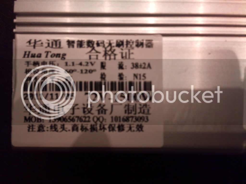
see the date on this controller.

Nov 5 2011...pretty new....

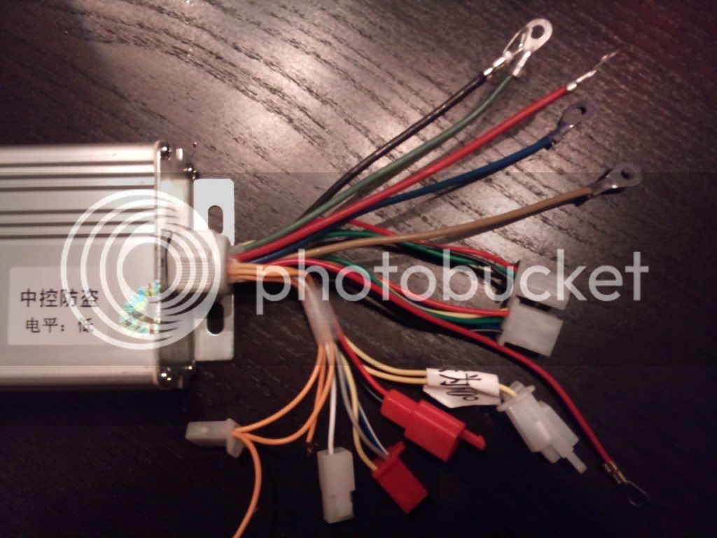
it appears i don't have any 3 speed wires

and inside is 3 shunts

what are all the orange wires?

DSC_0214.jpg


DSC_0215.jpg
 
Refer to the earlier posts, I put a diagram of what everything is. And you are correct, 3 shunts is right. and no, we never had 3 speed switch.
 
modder said:
see the date on this controller.

Nov 5 2011...pretty new....

it appears i don't have any 3 speed wires

and inside is 3 shunts

what are all the orange wires?
If it has the CA08 XM06AD_P04.1 controller board then you'll have to modify the insides for regen and/or a 3 speed switch. It's covered in this thread somewhere.
 
i have a 60v LiMn204 pack. i wired it in and it worked first try. :mrgreen:

it ran for a little bit but LVC kicked in and controller stopped :x

i'm ordering a 24v to run in series with the 60v. :D

this is the way it should be and i cannot wait. :mrgreen: :mrgreen:

so glad this worked pretty effortlessly. :mrgreen:
 
Edit;
I guess there is no HVC in this controller?
 
Does anyone of you guys have found a lower speed pad on the controller PCB ? I use the one that was found earlier but I was wondering if there was another lower one.
Thank you
 
need help modifying two controllers so that the LVC is set to protect a 48v lifepo4 battery 8AH golden motor style.

anyway I bought them a while back and im not sure which model this is but i took a picture of the sticker

hua tong sticker date.png

date is 2011/08/19 on the box and it has 3 shunts and a single orange wire without a connector on it.

anyway worryingly when i opened the first controller to check inside and see if i could recognise anything id seen on the thread i found some solder stuck to the board spanning a few resistors. Not knowing enough about electronics to know that though i thought it was a mistake or poor QC i was lucky to have the other controller to check against so i opened up that one too.

hua tong random solder.png

i checked against my other open controller

hua tong other controller no solder.png

no solder on there.

anyway removed it with some plyers and now i need some help to figure out which board i have and how do i put in a variable resistor mod to change the LVC on the fly.

Thanks in advance
 
I don't think this is the board in the subject line, CA08 XM06AD_P04.1. If it is, this is it;
http://endless-sphere.com/forums/viewtopic.php?f=2&t=26306&p=376677&hilit=changing+lvc#p376677
 
this controller have regenerative brakes? (feedbak energy)?

the max voltage are 100V? are good for the 9c?
 
I have question X about my controller.
Well read the FAQ, it will guide you through the basics of this controller. This FAQ is compiled from the collective knowledge of many members (A belated apology for not citing individual contributors: sorry there were just too many!), if you have something to add please pm me or comment on the thread.

Well what is this Hua Tong OT100?
That is the generic seller name for an expansive series of controllers built by Hua Tong/Ranton manufacturing. The majority of members bought their controllers for ~3X.XX USD from dhgate or alibaba. They also sell for 5X.XX USD on eBay.

Why is the cost so low?
Well primarily due to the miracle of chinese manufacturing. The downside is that you have no idea what you are getting. Explained further later.

What is this constant talk about different boards and dates of manufacturing?
Despite the outwards appearance of the controller. The internals of the controller can vary drastically. The best way to find out what board you have is to peek inside and look for the silkscreen'ed series name.

CA08 XM06AD_P04.1 is the first known iteration of the board. There have been 3 other iterations since (2nd Generation, C-D3.1, and C-D4.1)

The first generation and second generation boards were broadly similar. Assumed cost saving measures at manufacturing lead to the second generation using the IRFB4710 mosfets.
The third generation was a extreme departure from the first 2 generations. A new cpu and additional pads were added to the board.
Fourth generation (need more information)

How many MOSFETs are there?
The 72V version has 15 mosfets.

What type of MOSFETs are used?
CA08 XM06AD_P04.1 board IRFB4410 Mosfets were used
In later revisions of the board IRFB4710 Mosfets were used

Can this board be run without hall sensors / sensorless mode?
This board can not be run in sensorless mode.

What features does this board have?
Many of the boards features are only accessible by opening the controller and grounding pads to activate features

List of pads (First and Second Generation):
'X' is wheel lock in later versions, regen in the CA08 XM06AD_P04.1
'L' is reverse
'M2' is low speed**
'DS' 'SL' kill switch
'Q' is for cruise control

'SD' is disable motor (low speed) ?
'SL' is Low brake
'ZL' - 1:1 help ?

*please note that the pad names change between revisions
** only the 3rd generation has a three speed switch

Pads for the C-D3.1
Functions 1-8: need help

How do I turn it on?
Connect the small red wire to V+ (pack positive). This provides power to the low voltage section of the board

Is there a HVC?
No, there is not. Usually, over voltage situations lead to blown mosfets and gate drivers. Use higher voltage with caution.

Then what is the highest voltage that I can run?
The mosfets and capacitors are rated at 100V. As such, many members have reported success with voltages at or slightly higher than 100V. Many believe that 22S ~92V is optimal as it allows for regen and is safer for the mosfets.

LVC?
~60V. It is easily modifiable.

Is there Regen?
Pack Voltage must be under <90V, so 22S is optimal. I've never actually run regen could someone cover this?

How do i raise or lower the peak amperage?
To raise the peak amperage, add additional solder to the shunts (3 exposed, silver, [thick] wires on the top left of the board). To decrease the peak, remove parts of the shunt by cutting or grinding or an entire wire from the shunt for a large percentage drop.

What is the peak wattage that I can run?
This depends on a lot of factors that can't all be covered in this FAQ. I personally run a slow wind motor on a large diameter wheel at peak power levels close to 6kW. I've also blown up my board lots of times. I doubt that you could push much more wattage through the board with any reliability.

Does it have programming ability?
Definitly no to the programming. Although there has been a programming header in every revision of the controller you would need to know the cpu and be able to dump the firmware, not to mention figure out the machine code.

Will it run my motor?
If your motor is a brushless 3 phase motor then yes!

Is there a Cycle Analyst plug.
Nope. A member has been able to create a custom CA plug

What are all the plugs? I did not receive documentation.

First, Second and Fourth Generation Plugs.
xp4j6c.jpg


Alarm (4 pin, 3 populated): One wire has 5v, another has your battery + voltage, and the third is ground. Use it for a voltmeter if you'd like

Hall Sensor (6 pin, 5 populated) Black: Gnd, Red: 5V, Yellow/Green/Blue: Sensor Output corresponding to Phase

Throttle (3 pin): Warning! – Wires in connector may be reversed. Black: Gnd, Red: 5V, Green: Hall output (0-5V)

60/120 wires (2 pin): Auto its 60, if your motor runs weird, try 120 by connecting the two wires together. If you don't need them connected, simply snip them away.

Ignition: This can either be wired to a switch, that goes to your power supply +, or you can connect it directly to power supply + if you wish to have no switch for ignition.

Voltmeter (2 pin): This is simply wires that tell you how much battery/pack voltage you have, so you can lead these to a voltmeter if you want, or snip them away. Another use of the voltmeter wires is a DC-DC converter so you can run your aux lights/fans. Black: Gnd, Red: Pack/Battery Voltage

Third Generation. Additional plugs only
file.php


3 Speed (3 pin): use a SPCO switch. (only on the C-D3.1)

Reverse (2 pin): Gnd to put the bike in reverse Black: Gnd, Green: Reverse (only on the C-D3.1)
*only on the C-D3.1

Cruise Control: Wire a momentary switch to it, and lead it to ground. When pressed, cruise control is enabled.

Controller not working?

Blink codes
1 flash: Standby, motor stopped
2 flashes: Throttle input fault or HV brake active
3 flashes: Locked rotor (start speed protection)
4 flashes:
5 flashes: High side FET shorted
6 flashes: Hall sensor fault
7 flashes:
8 flashes: Under voltage (LVC) active

Precharge
I personally use about ~200 ohms as my resistance figure. This website provides detailed information and a pre-charge calculator
 
Back
Top