• Howdy! we're looking for donations to finish custom knowledgebase software for this forum. Please see our Funding drive thread

Adding sensors to a Astro 3210 motor

Burtie,

I was wondering about the back EMF generated by the Astro with distributed windings.

Not trying to be a bother, but, Would it be too much trouble to ask if you would to spin the Astro with a drill and scope/monitor
the phase leads to see what the waveform looks like.

It appears to be a double hump sinuisoid from watching your video....but seperating the controller waveforms would help see the raw BEMF.

:D
 
OK,
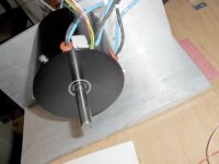
I connected the motor to the 'scope like this:

Raw connections.jpg

Spun it up with the drill, to see this:
( I know it starts a bit scary, but it gets better :) )

http://www.youtube.com/watch?v=I_fGepS3TBI
[youtube]I_fGepS3TBI[/youtube]


It does indeed appear to be a double hump sinusoid as you suspected.

Burtie.
 
:: waves back :: hiya Burtie :mrgreen:

KiM
 
I didn't expect such a quick reply!!!
You're a gentlemen Burtie, much obliged. :mrgreen:
Thanks for the virtual lab!

Yea, you kind of look like the ominous ghost in the scope at first.... :lol:

It looks like a hybrid trapezoid double hump sine waveform. Cool. 8)

I would guess that if there were more poles and more distribution to the windings that the wave would tend to be more sinusoidal.
 
12p3phPMDC said:
I would guess that if there were more poles and more distribution to the windings that the wave would tend to be more sinusoidal.

I think the humps are caused by sharing poles, not lessened by it. I've only ever seen clean sinewaves from motors that wrap 1 pole at a time.
 
liveforphysics said:
12p3phPMDC said:
I would guess that if there were more poles and more distribution to the windings that the wave would tend to be more sinusoidal.

I think the humps are caused by sharing poles, not lessened by it. I've only ever seen clean sinewaves from motors that wrap 1 pole at a time.

Yea, that actually makes more sense. Due to each pole having an individual contribution to the BEMF. thanks for that correction :D

From looking at the pics the windings are distributed across three poles. So how would that generate the double hump?
Would the voltage peak when a magnet is centered in the slot? 3 poles, 2 slots = double hump?

I wonder how the BEMF will change when the motor is actually terminated in Y or Delta. :?:

Burtie seems to have isolated a single phase and shown the BEMF from it. That has to be the simplest BEMF waveform because you'll have less interactions between phases.
And no circulating currents are possible in that config. Any thoughts?
 
It can't be that simple. Like Luke, I've only ever seen sine waves out of the motors I've tried this with. If you take any combination of sine waves at the same frequency, you always get another sine wave.

The waveform Burtie showed looks as if it has a 3rd harmonic in there. You can't generate that shape by adding staggered sine waves.

I suppose its possible that the magnets are arranged so that the flux through the poles doesn't vary sinusoidally.

Nick
 
Tiberius,

True....

Since Burtie had the phases isolated, where is the third harmonic coming from? The magnetic circuit I suppose?
 
Burtie wrote:
There seemed to be no acceptable compromise between the delta and wye hall group positioning that would work well for both configurations.
I am not so sure this is true now...

The other day, I took apart the wiring between the motor and the controller, so that I could insert a Delta-Wye switching unit (D-Y switch shown here
http://www.endless-sphere.com/forums/viewtopic.php?f=28&t=15344#p249091 )

When I re-wired the system, I ran through the same test as before, looking for the optimum timing positions for the two modes. To my supprise I found that the angle between the two optimum positions was now only about 4 degrees, where previously it had been 12 degrees.
Because the angle is small, it means that there is a good position that works well for both modes.

I am not sure why the picture has changed :? . I used a different sequence of phase wiring than before for the delta mode, which in turn meant i needed a different hall sensor sequence, which I found by trial and error. I now find that the Delta timing is at a point 4 deg retarded in relation to the Wye timing, whereas previously it was 12 deg advanced.

:? errrr?

Burtie
 
Did you terminate your phase ends differently? I have a sneaking assumption that you may have had one phase wired in backwards from the rest on the first test. This would be like having all blue ends together for Wye in one instance, but having two blue and one black end together for another Wye termination. Delta has the same possibility.
 
I was careful to terminate the phases correctly in both cases. I connected the blue wires to the controller phase outputs and tied all the black wires together to configure Wye.

To configure Delta, I left the blue wires where they were, separated the black wires and paired each one with a blue wire. There are six combinations you can choose here:
One shorts each winding to its-self so does not work,
Three combination short one winding so will not work.
The remaining two combinations will work, providing of course you have the correct hall sensor sequence and position.
 
...continued from previous post.

Without altering any other wiring, the two delta combinations will both run the motor in the same direction as the Wye setup that we started with.
One of the delta combinations appears to be optimised at 4 mechanical degrees (16 electrical) retarded, the other at 12 mechanical degrees (48 electrical) advanced, relative to wye.

From everything I have read, I would expect a 30 (electrical) degree angle between D and Y modes (equivalent to 7.5 degrees mechanical). i.e. 7.5 degrees retarded for one delta combination and 7.5 degrees advanced for the other. It is the assymetry I dont understand.


Wait........I think it just clicked!!! :shock:

-If the motor was static, the offsets would be symmetrical for the two combinations. It is because the motor is spinning that it likes the timing to be more advanced.
The faster it spins, the more advance it likes, just like an internal combustion engine. Because it spins faster in delta, it likes the timing to be more advanced than when it is in wye.

Make sense to anyone else??


I may seem a bit obsessed with this stuff at the moment, but the reason I want to understand it is so that I dont get 100 or so sensor plates made with the slots at the wrong angles! :)

Burtie.
 
Burtie,
I know your using a little 6fet controller to test what you are doing, Have you ran anything upto 50v using it with one of your modded motors without any problems ?. There are a few people having issues with the newer 6fet controllers running at 48v on modded outrunners, Just thought I would ask.

Cheers.
 
gwhy!

I have not run this astro, or any of the 6 FET controllers beyond 24v yet.
But I have seen similar problems with my 12 FET controller + outrunner on the Stinkey @50v, when pulling >80 amps.

I have posted a bit in the outrunner thread about it:
http://www.endless-sphere.com/forums/viewtopic.php?f=30&t=15686&p=252033#p252033

Burtie.
 
I have had some limited success with getting my 3220 to run on hall sensors. I made a fixture similar to Burtie's but I have it on the inside and am using the magnetic field coming out the side of the rotor. The video attached explains it.

[youtube]WqO2NkT_4o0[/youtube]

http://www.youtube.com/watch?v=WqO2NkT_4o0
 
Drew,
You beat me to it! :wink: Good to see that it works without needing extra magnets.

I think this internal solution is potentialy much more practical / cheaper / verstile / easier to produce than the external setup I have been playing with.

Nice job :D

Burtie
 
Drew,
Gwhy,Jerremy H, & matt-n-mtl. have been di-secting the cutting out issues on our mini controllers (6FET infineoins)
& have a couple items zeroed in on. Just a few tweeks & the cut out issues are behind us. Hopefully with some of the safety features still intact.

its all in this thread:
http://endless-sphere.com/forums/viewtopic.php?f=2&t=16910
 
I have been following that thread. I just got my programming cable from Lyen, just need the time to hook it up and then try some of the settings.
 
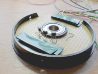
Inspired by drewjets video, I tried fitting sensors inside the astro too.
It turned out to be a pretty fiddly job to get the timing right :x , but it works well on the bench now :) .

I had a couple of attempts at fixing halls to a circular piece of strip board that was machined to fit inside the end cap.

First attempt.jpg

The second attempt worked better.
I needed to get the sensors further away from the stator fields.

Astro back plate.jpg
Backplate2.jpg

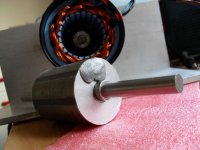
Hall positioning was complicated by having to avoid a large lump of snot stuck to the end of the rotor, -presumably for balancing.

Lump of snot.jpg

Sensor leads.jpg

To sum up:
wye current was 0.6 A, delta current was 4 A (was 0.6A and 3.5A with external hall setup and also with sensorless controller), so efficiency looks pretty similar so far. With This method it took about 1 hour to make the parts and the rest of the day trying to get the timing right! -sort of the opposite way round to the external method.

I can fit both internal and external sensors to the same motor, so should be easy to do a proper comparison of performance when it is fitted to a bike.

Edit update:
This internal fitment does not work well in practise, it is upset by the magnetic field from the stator
See more info later in the thread here
http://endless-sphere.com/forums/viewtopic.php?f=30&t=14210&start=180#p545457

Burtie.
 
Awesome Burtie. I really like the idea of them inside. For one it elliminates the need for an extra magnet ring and also protects the Halls.

Do you think there is anyway I could get the timing done without a scope?

Also I have seen the PC based scopes, would they work and how much do they cost?
 
I dont use a 'scope to set up the timing. I just rotate the sensor group carefully while the motor is running and look for the position where least current is drawn.
Of course you need to get the timing pretty close before using WOT or you risk drawing destructive amounts of current 8). I always put a 10 amp fuse in the supply when doing this now (after learning the hard way :oops: ).

I think USB scopes are a great idea, I promise myself one day when I save up I will buy one! Not sure my old craptop is up to it tho :roll: .

I dont know what they cost, anyone got any recommendations?


Edit: forgot to ask was that astro wired in delta or wye in your video? If it was delta, the current figures look ok, you would have the timing spot-on.
Burtie
 
For the USB scopes, I used a TiePie for years and it was great but they are a bit pricey at about 1000GBP for the high frequency unit, might be more now that the pound is worth nothing... :( Pico Scope are also supposed to be very good and they start at very reasonable prices. The tiepie I used was every bit as good as a bench scope of similar cost IMO. They are so handy and I really wish I would have bought 1 instead of rushing out and buying a bench scope a couple of months back.
 
Burtie, I am wired in Y, that is why I know my amps are too high. It looks like you machined away the cutouts for the power wires on the Astro, was that to make it easier to time it, by being able to rotate while it is running. I am not 100% sure I am exactly on 30 degree spacing as well. I used a 30 60 90 triangle to make my holes then drilled by hand. Fine for expermenting, but needs accuracy for real use. I am hoping you come to a final config you are happy with and then buy one from you.

Cell Man, would this scope http://www.picotech.com/picoscope2200-specifications.html be appropriate? I have never used one and only seen them in person a few times. I don't really want to spend $260 for something I wouldn't use much, any of them around $100?

How about something like this one? http://www.virtualvillage.com/5-channel-portable-pc-usb-2-0-oscilloscope-cd-001482-006.html?utm_source=googlebase&utm_medium=shcomp
 
The cheapest 'scope I've seen that is just about fast enough for ebike controller work is this one: http://www.seeedstudio.com/depot/dso-nano-pocket-size-digital-storage-oscilloscope-p-512.html?cPath=11&zenid=5e81df9c287a5067519e6bfae39e7e00 for $89. It has a USB connection, so can dump files to a PC. I built it's cheaper predecessor, this one: http://www.seeedstudio.com/depot/digital-storage-oscilloscope-diy-kit-with-panels-p-515.html?cPath=71 which is currently $33 as a kit. It's just about fast enough for general ebike controller work, but could do with a bit faster sampling rate to be able to see transient events a bit better. It doesn't have a USB port, but connects via a serial port and can only dump screen shots as BMP files.

Jeremy
 
drewjet said:
I have had some limited success with getting my 3220 to run on hall sensors. I made a fixture similar to Burtie's but I have it on the inside and am using the magnetic field coming out the side of the rotor. The video attached explains it.

[youtube]WqO2NkT_4o0[/youtube]

http://www.youtube.com/watch?v=WqO2NkT_4o0

Drewjet,

Any recent developments with the Hall sensors inside your 3220? I got my 3220 and will be opening it up today. Looks like I should set the sensors up vertically spaced 30 degrees and try to null unloaded current. Did you get yours working well?

Dave
 
Back
Top