Analysis of regen on an ebike

In general, the deeper the cycle, the fewer cycles the battery will last. For Nimh, if the state of charge is kept between 20%- 80% there seems to be no practical limit to the number of cycles the battery will last. Most other chemistries are similar. Cell damage tends to occur when the cells are over charged or over-discharged. In a Nimh pack with lots of cells and no BMS, it would be easy for one cell to get weak and be reverse charged during a discharge cycle, destroying it.

Since the best you can get out of regen is way less than 50%, unless you live at the top of a hill, it would be nearly impossible to get a situation where the batteries couldn't absorb the regen charge. To make things idiot proof, you would still need to manage this possibility. You can either stop regen if the batteries get too high, or use some kind of dump load resistor to dissipate the excess. Either of these could be triggered by a BMS circuit if one was present.
 
fechter said:
Since the best you can get out of regen is way less than 50%, unless you live at the top of a hill, it would be nearly impossible to get a situation where the batteries couldn't absorb the regen charge. To make things idiot proof, you would still need to manage this possibility. You can either stop regen if the batteries get too high, or use some kind of dump load resistor to dissipate the excess. Either of these could be triggered by a BMS circuit if one was present.
Methinks idiot-proof is what is needed for the masses! For people not understanding what's involved with regen, this situation could happen all too often. Imagine someone pulls their ebike off the charger with the pack not well balanced, then rolls down their driveway using regen to brake them. With no cell-based over-voltage signal available to the controller, one cell's voltage may rise enough to damage it very badly very fast - specially if the hill is big enough to generate strong regen currents.

I suppose that a simple battery level over-voltage protection would be enough to protect all the cells in the battery under many circumstances, but it's not idiot-proof. Setting the controller's over-voltage regen cutoff limit lower than total full charge might be good enough too, since the cell's voltage rises quite fast at the end of charge. I would still be nervous about one unbalanced cell being overcharged in such a situation though, specially if the pack is getting older and is prone to having it's cells fall out of balance.

Do you think a cell-triggered OVP going to the controller signal would be overkill? It would be pretty simple and would make regen more robust IMO. We are talking about very expensive batteries here after all...
 
solarbbq2003 said:
nice one justin!
another interesting thing is you can capture more regen when the batteries are more discharged, its quite noticeable, I guess the batts have lower resistance the more discharged they get and hence can capture more regen current

Is that really the reason? I think many batteries increase in ESR as they are discharged.

Perhaps you might be seeing one of these:

1) When a cold battery warms up, often its ESR goes down. Discharging a battery at a good rate will warm it.
2) At a given pulse width, a low voltage battery will take more current than a high voltage one, since the voltage differential will be higher between back EMF and battery.
3) Most controller designs start to self-regen above base speed, and thus will start sooner the lower the battery voltage is.
 
snowcrow said:
Would a lower system voltage (36v or 48v), be more effective % wise, when using regen?
Blessings, Snow Crow

Since a regen controller inherently does synchronous rectification, the answer is basically no. The difference in regen efficienty with a 36V pack vs a 48V pack would be too small to measure, since the switching losses would be more or less the same, and the conduction losses on the motor->controller side would be the same as well.

Justin
 
solarbbq2003 said:
nice one justin!
another interesting thing is you can capture more regen when the batteries are more discharged, its quite noticeable, I guess the batts have lower resistance the more discharged they get and hence can capture more regen current,

This is not something that I have observed in the regen controller that I was using, although I could see it being the case if either a) the controller has an upper voltage limit on the regen, and it will scale back the peak regen amperage so as not to exceed this voltage, or b) it is implemented to go down to a fixed PWM duty cycle so that with a lower battery voltage you'd naturally wind up with a lot more regen current.

On the tests I was doing, the controller firmware is designed such that the regen throttle is directly regulating the magnitude of the regen phase current through the motor, so direct braking torque control, and it will dump the ensuing energy into your battery regardless of the state of charge or voltage of the pack. You do get more regen amp-hours when the battery is flat than when it is charged, simply because at a lower voltage the same amount of regen energy is transfered at a higher current but a smaller voltage.

But the idea of a battery being able to 'capture' regen current is not a term I would use and is a bit misleading. If the controller feeds regen energy to the battery, the battery will have no choice but to take it.

Justin
 
paultrafalgar said:
Justin, could you improve the regen capture by using an ultracapacitor as intermediary, with an ultracapacitor such as JCG uses here:
viewtopic.php?f=6&t=7511&start=0&st=0&sk=t&sd=a&hilit=JCG

I think that my first reply perhaps didn't quite address what I think you were getting at so I'll try again here. One of the main reasons that ultracapacitors are touted is because of their ability to absorb very large currents that a battery couldn't safely handle. For instance, an ebike and a rider (~100kg) together moving at say 40 kph have a kinetic energy of about 6kJ, and if you wanted to come to a stop in say 2 seconds, then that means absorbing some 3 kW of power on average. No ebike battery could take 3kW of charge current, so better absorb that with an ultracap right?!

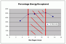
But what I was showing with parabolic regen battery current curves is that for high rates of regen braking, the amount of regen current that actually flows back into the battery starts to decrease with higher braking forces. If you want to come to a fast stop, then just short all the windings, and you don't have to worry about any excessive recharge currents damaging the battery. This also illustrates how if you do want to come to a fast stop, the efficiency of the regen is quite poor, simply because high regen torque means massive amounts of I^2R losses in the motor winding, so increasing the rate at which you can recapture energy (as supposedly an ultracap would allow) actually decreases the total energy you end up getting. On the curve that showed the % of kinetic energy recaptured, you can see that beyond 12 amps of regen current, sure I could come to a stop faster and waste less energy to wind and rolling drag, but I would actually get fewer watt-hours back in the source because the generating efficiency is pretty low at these kinds of currents.

So even if an ultracap would allow me to do a maximum regen current of say 20 amps. Yes, I would be able to do more regen and come to a faster stop, but no, I would not get any more energy back. In fact, I would recover quite a bit less energy than had I come to a more gradual stop at 6 amps regen using just a battery to absorb the energy. So the idea that an ultracap could help 'improve' the percentage of recaptured energy is quite false in this case.

It is interesting to note that for similar reasons, if you have both mechanical brakes and regen brakes and need to come to a quick stop, you can actually get more energy back to the battery by using both the mechanical and a more modest regen together, than you would coming to that stop purely on regen alone.

Justin
 
Thanks a lot Justin for that erudite exposition. Slight off topic, but I notice from your sig that you're installing a NuVinci on your new bike; I was very interested in that kit but various people have convinced me that they are inefficient including Miles whom I have great respect for (eg. http://endless-sphere.com/forums/viewtopic.php?f=2&t=7891&p=119269&hilit=NuVinci#p119269). I'd love to hear your opinion on that. Perhaps the way to do it would be in a build-thread on your new bike.
Thanks again,
Paul
 
justin_le said:
But what I was showing with parabolic regen battery current curves is that for high rates of regen braking, the amount of regen current that actually flows back into the battery starts to decrease with higher braking forces.

When seeing those current curves I was thinking of another kind of generator, a PV solar cell which will also will give you max current at short circuit but zero power out.
You want to pick an operating point at the I/V knee maximum power point.
As with any generator, an audio amp being another example, max power transmission occurs when the load impedance is matched.
It seems like an ultracap would be much lower impedance & relatively speaking, like dumping the power into a short.
 
Toorbough ULL-Zeveigh said:
justin_le said:
But what I was showing with parabolic regen battery current curves is that for high rates of regen braking, the amount of regen current that actually flows back into the battery starts to decrease with higher braking forces.

When seeing those current curves I was thinking of another kind of generator, a PV solar cell which will also will give you max current at short circuit but zero power out.
You want to pick an operating point at the I/V knee maximum power point.
As with any generator, an audio amp being another example, max power transmission occurs when the load impedance is matched.
It seems like an ultracap would be much lower impedance & relatively speaking, like dumping the power into a short.
They call that MPPT for maximum power point traking, in the solar scene.

Having the controller itself programmed for this type of regen optimization is exactly what I want to do. I decribed it as "- Regen on demand (with some automatic current adjustment done by the controller to optimize efficiency)" in my controller feature thread, but I think I'll change the wording to something similar to regen MPPT. This is pretty much what Justin was doing manually during his excellent regen analysis - not setting the duty cycle too high nor too low, depending on the instantaneous ratio of motor voltage to battery voltage. This should help in getting better regen efficiency no matter what the user does (or overdoes) with the regen throttle.

As for the ultracap vs motor impedance issue, I don't think it's really like dumping into a short. The controller is actually doing the impedance matching between the motor and the battery / capacitors (by using PWM with motor inductance and battery capacitance). This is what the MPPT controllers used for solar are actually doing already. As a side note, the few ultracaps for which I've read the datasheets seem to have not-so great ESR, not really any better than LiFePO4 batteries it seemed to me at the time. Please correct me on this if I'm out of date with the cap situation!
 
ZapPat said:
As for the ultracap vs motor impedance issue, I don't think it's really like dumping into a short. The controller is actually doing the impedance matching between the motor and the battery / capacitors (by using PWM with motor inductance and battery capacitance). This is what the MPPT controllers used for solar are actually doing already. As a side note, the few ultracaps for which I've read the datasheets seem to have not-so great ESR, not really any better than LiFePO4 batteries it seemed to me at the time. Please correct me on this if I'm out of date with the cap situation!

You can't argue with Justin's curves. At one end of the spectrum, the duty cycle of the braking switch gets high enough for the inductors to reach steady state. Whatever the opposite of discontinuous is? If you restrict yourself to the efficient range, the braking force will drop off as you slow down and may result in too much charge current under fast braking.

A MPPT-like scheme could work and would maximize energy recovery under some conditons, but I think it would result in less than ideal driveability characteristics. I would rather sacrafice some efficiency to get optimum driveability. Improved, safer braking takes priority over energy recovery. The overall energy recovery is so low that even if it was optimized it would still be pretty low.

I found constant motor current braking to be nearly ideal in terms of driveability and it limits the drivetrain torque to prevent damage. On my Zappy (synchronous switching), the braking force would remain constant until the speed was almost zero.
 
fechter said:
On my Zappy (synchronous switching), the braking force would remain constant until the speed was almost zero.
For clarity, was the force constant or the rate of deceleration? (less force being needed as the vehicle slows)
 
TylerDurden said:
For clarity, was the force constant or the rate of deceleration? (less force being needed as the vehicle slows)

The force was constant.

Braking force is directly proportional to motor current. By keeping the motor current constant, the braking force remains constant. If the braking force was too high on my setup, it would cause the belt to skip teeth. I normally adjusted the limit to just below where the teeth would start skipping. If I adjusted the limit to zero, it would behave like very low resistance free wheeling.
 
fechter said:
You can't argue with Justin's curves. At one end of the spectrum, the duty cycle of the braking switch gets high enough for the inductors to reach steady state. Whatever the opposite of discontinuous is? If you restrict yourself to the efficient range, the braking force will drop off as you slow down and may result in too much charge current under fast braking.
A MPPT-like scheme could work and would maximize energy recovery under some conditons, but I think it would result in less than ideal driveability characteristics. I would rather sacrafice some efficiency to get optimum driveability. Improved, safer braking takes priority over energy recovery. The overall energy recovery is so low that even if it was optimized it would still be pretty low.
I found constant motor current braking to be nearly ideal in terms of driveability and it limits the drivetrain torque to prevent damage. On my Zappy (synchronous switching), the braking force would remain constant until the speed was almost zero.
You're probably right about the driveability being under par for this type of controlled regen... but I'll have to try it out anyways! Justin did observe that by using a combination of regen and regular breaks together, we could actually get more energy back than with regen alone. I guess an MPPT-like regen used along with the regular breaks would illustrate exactly this situation! Anyways, maybe some type of compromise could be found, and if I do decide to keep an MPPT-like regen mode it would definitely be optional only via user-interface software, with constant motor side current regen being the standard mode. And of course it would be city users (stop and go) and hilly area users that would benefit from this mostly, making efficient regen a no-brainer when this mode of regen would be selected.
 
Don't forget ZapPat that maximum power-point regen is almost by definition only 50% efficient on the electrical side, it's not really where you want to be. A controller that defaults to this state wouldn't deliver as much back to the battery as a proportional regen system that is generally well to the right of the max power point where the regen efficiency is much higher (even if the braking force is somewhat less). Ideally the rider anticipates stopping far enough in advance that they can come to a stop on regen alone, while keeping the duty cycle somewhere between 75-85% of what it would be to match the back-emf voltage.

If you are operating anywhere to the left of the MPPoint on that curve, then you are better off reducing the regen so it moves right to the MPPT point and making up for the difference in stopping power with mechanical brakes. This way you would come to stop just as fast but you would get more amp-hours back into the battery.

-Justin


ZapPat said:
You're probably right about the driveability being under par for this type of controlled regen... but I'll have to try it out anyways! Justin did observe that by using a combination of regen and regular breaks together, we could actually get more energy back than with regen alone. I guess an MPPT-like regen used along with the regular breaks would illustrate exactly this situation! Anyways, maybe some type of compromise could be found, and if I do decide to keep an MPPT-like regen mode it would definitely be optional only via user-interface software, with constant motor side current regen being the standard mode. And of course it would be city users (stop and go) and hilly area users that would benefit from this mostly, making efficient regen a no-brainer when this mode of regen would be selected.
 
ZapPat said:
[...]Justin did observe that by using a combination of regen and regular breaks together, we could actually get more energy back than with regen alone. I guess an MPPT-like regen used along with the regular breaks would illustrate exactly this situation! Anyways, maybe some type of compromise could be found, and if I do decide to keep an MPPT-like regen mode it would definitely be optional only via user-interface software, with constant motor side current regen being the standard mode. And of course it would be city users (stop and go) and hilly area users that would benefit from this mostly, making efficient regen a no-brainer when this mode of regen would be selected.
justin_le said:
Don't forget ZapPat that maximum power-point regen is almost by definition only 50% efficient on the electrical side, it's not really where you want to be. A controller that defaults to this state wouldn't deliver as much back to the battery as a proportional regen system that is generally well to the right of the max power point where the regen efficiency is much higher (even if the braking force is somewhat less). Ideally the rider anticipates stopping far enough in advance that they can come to a stop on regen alone, while keeping the duty cycle somewhere between 75-85% of what it would be to match the back-emf voltage.
If you are operating anywhere to the left of the MPPoint on that curve, then you are better off reducing the regen so it moves right to the MPPT point and making up for the difference in stopping power with mechanical brakes. This way you would come to stop just as fast but you would get more amp-hours back into the battery.
-Justin
I think we are actually saying the same thing here Justin - I guess I am not being very clear. My idea of the MPPoint, or maybe more rightly called the M.P. Area, is as seen from the battery side of the controller, not the motor side. The "MP Area" will change with travelled speed, so as the bike slows down the controller would be dynamicaly changing the duty cycle to stay in this efficiency area. Here is one of your gifs I moded to give you an example:
Kinetic Recapture Efficiency (regen - MPPoint).gif
As I see it, the red area would be the MP Area at a given speed.
I don't quite get your statement "Don't forget ZapPat that maximum power-point regen is almost by definition only 50% efficient on the electrical side, it's not really where you want to be.". According to your own gif here, you did not go much over 50% recaptured even with the best duty cycle setting. It seems to me that the principal of MPPT is to maximize energy transfer between a source and load, and as such would be our goal, no?
*EDIT*
I re-read your posts again, and maybe now have a better idea of what you mean. Here's another of your pictures from this thread (edited also).

The green lines give maximum battery current during regen for each speed, but if I understand you correctly, maximum efficiency would be more like where the blue arrows point to... is this right?
And if I understand correctly, the maximum efficiency regen throttle setting would be situated midway between the max current setting and another point that is limited by the bike's frictionnal losses (air+rolling). Any idea of how this could be calculated in firmware?
I appreciate your patience!
Pat
 
So the maximum efficiency point is not the same as the maximum power point.

MEPT?

To implement this, you would need a circuit that can determine the maximum efficiency point. This might require some emperical testing and a lookup table in the MCU unless there is an analog way to find it.
 
ZapPat said:
dennis said:
ZapPat said:
- Smoother braking action (when using current based regen with space-vector modulation)
All of the above is true, except for the smooth part. With my Bionx system, I found that when braking the whole back wheel vibrates during regen and the back and forth torque placed on the rear axel will cause the nut to loosen over time. I always check my nuts now before each ride :wink: A good solution maybe a custom rear axel for electric hub motors...larger locking nut with a cotter pin with more surface area, similar to an off road motorcycle.... and if you like to track stand http://en.wikipedia.org/wiki/Track_stand, the way the hub sticks when regen kicks in, makes track standing much harder but is possible.
I would agree with you on this point for regular regen, but as you see I did specify using SVM which reduces torque ripple both during drive and regen. This happens because a SVM capable controller will output a waveform that matches the motor's own back EMF, thus avoiding the uneven current flows that regular trapezoidal commutation produces. This of course does require more complexity mostly in firmware, more processing power, faster ADCs and phase current sensing. I must admit I have no idea what biox uses as a regen technique, but from what you say they must be using regular old commutation techniques.

Of course even with SVM we still have the bidirectionnal torque issue (although probably lessened with the smoother SVM) caused by regen. This will just be a matter of having good torque arms, along with some setup that will effectively lock your nuts to prevent them from loosening. I'm not a hardcore bike guy, so I'll leave this part for other great brains here to solve. Note that Justin just tighted the hell out of his nuts and that was already enough for his setup to not come loose, so I don't think that the solutions will be that complex.

dennis said:
Regen, imo also reduces the useful life of the battery, in my case is LiMn which has a useful life of about 500 full cycle charges. With heavy use, my 9ah battery was only able to hold less than half a charge after 1.5 year. That is why I'm so interested in super capacitors. If someone can put it in a kit without adding too much weight. my 1/100 cent....
Read Justin's posts, along with mine, then explain why you claim that regen inherantly reduces battery life when current limits and such are well thought out? In other words, explain what is the difference between regenerated current and regular charging current going into the battery? Also, what makes you sure that something else was not the cause of your packs premature demise? I know I might sound rash a bit here, but I strongly dislike unsubstantiated claims being posted by a few people and then repeated by many others... :evil:

Cheers!
Pat

There is no difference I can reasonably think of between regen current and regular charging current going into the battery. I guess I need to clarify my above statement with a few more statements & questions. It takes about 2.5 to 3 hrs to fully charge a depleted LiMn Bionx battery. How would the battery absorb the high amps created during hard regen braking, if it only accepts a slow trickle charge. What happens to the high amps dumped during hard regen braking so the battery will not be damaged. That is where capacitors has an advantage in my opinion. I'm not an electrical engineer, but just from tinkering with discarded parts of disposable cameras in my youth when I worked for a film developing company, I saw how tiny capacitors charged up in the matter of seconds from a AA battery & quickly discharged to create a flash. I could see an advantage here over any battery available today & if they do not age like our currently available batteries, this is the solution we are all looking for.

The main reason I joined in this discussion is just to add a bit of by the seat of my pants experience with the Bionx regen system. Another question ...if the full cycle charge/discharge life for a Bionx LiMn battery is 500, how will numerous minute regen charges affect the cycle life of the LiMn battery? I have been testing/discharging the packs deeply but not to the point of power cut off, I would always leave at least a bar left on the console before swapping batteries. Is the aging of the battery due to abuse, not really. Overcharged cells, not possible when an overcharging prevention circuit is built into the charger. LiMn battery's intrinsic self degradation due to age? I'm sure all of these factors contributed to the shortened life of the Bionx battery.

In short http://www.afstrinity.com/xh.htm ...a scaled down version is what I have in mind for bicycles or even better a fully enclosed tilt steering electric moped or motorcycle http://www.aptera.com/, if they are at all feesible (note: fully enclosed would be a nice design, I have been caught in the rain many times when I used to commute via a Kawasaki ZX-6 one hundred miles per day for eight years & getting soaked by rain like a hosed dog is not fun.) I'm just a hobbyist interested in a new mode of personal transportation that would be an environmentally friendlier option to what we have available today.

Cheers! Dennis
 
fechter said:
TylerDurden said:
For clarity, was the force constant or the rate of deceleration? (less force being needed as the vehicle slows)

The force was constant.

Braking force is directly proportional to motor current. By keeping the motor current constant, the braking force remains constant. If the braking force was too high on my setup, it would cause the belt to skip teeth. I normally adjusted the limit to just below where the teeth would start skipping. If I adjusted the limit to zero, it would behave like very low resistance free wheeling.

I would refer my learned colleague TD to Newton's Second Law.

Nick
 
justin_le said:
If you are operating anywhere to the left of the MPPoint on that curve, then you are better off reducing the regen so it moves right to the MPPT point and making up for the difference in stopping power with mechanical brakes. This way you would come to stop just as fast but you would get more amp-hours back into the battery.

You would also be dumping the heat into the brakes instead of the motor windings, which could be a major consideration with a lot of stop go riding.

I think there is some confusion over
Maximum Power Transfer
Maximum Efficiency (difficult to define)
Maximum Braking Force

These are all different from the best strategy for recovering energy. For instance the best efficiency of conversion from motion to battery Ah happens at low braking effort. But if you brake too gently, the energy will bleed off as aerodynamic losses instead.

Nick


Nick
 
As Justin pointed out, regen and non-regen controllers are basically identical. All that is missing is switching of the mosfets to resist rolling and cause a braking effect.
And we all know that reverse rotation of a powered hub motor has resistance to turning. In reverse, this is the switching required for regen.
Alot of the immediate start chrystalite controllers that Justin sells have reverse with a key switch. I disconnected this on mine because the keyswitch was shorting out in the wet and going into reverse.
If the reverse pulse pattern is what regen is, then why not hook up a brake switch to the reverse input for braking? Anyone try this?
 
I read most of this thread, and I can say that I like the idea of regen. Perhaps the future will rpvide more efficient regen controllers which provide better results and more ease of use.

With my current build, I am going for regen with a Kelly controller.

However, the #1 reason for me wanting regen, is simply because I like the braking idea. I like the idea of braking from high speed without eating up my brake pads. With a long commute to work, with alot of flats and hills, I can concievably use my regen up to 80% of the time for my braking, and save my brake pads and subsequently the rims from heavy wear over years of use.
 
Affliction said:
And we all know that reverse rotation of a powered hub motor has resistance to turning. In reverse, this is the switching required for regen.

This isn't quite correct. The analog Crystalyte start immediate controllers are wired in such a way that one low side mosfet is always engaged and shorted to ground. When the motor is spun forwards this has really no consequence, since the grounded motor phase is the one at the lowest voltage. However, if you attempt to spin the motor backwards, the grounded phase is actually the motor phase that has the highest voltage relative to the other two, but it is still being forced to ground, and as a result you end up with circulating currents that flow through the clamping diodes of these other phases and ground. This has pretty much the same consequence as shorting all the phases together. It does slow you down electronically, but it's not exactly regen since there is nothing flowing back into the battery pack when you do this.

Alot of the immediate start chrystalite controllers that Justin sells have reverse with a key switch. I disconnected this on mine because the keyswitch was shorting out in the wet and going into reverse.
If the reverse pulse pattern is what regen is, then why not hook up a brake switch to the reverse input for braking? Anyone try this?

If you were disciplined enough to never touch the throttle when you reversed the direction switch on the controller, then yes you could have a simple on/off electronic brake, but the braking force at speed would probably be excessive. If you were then to actually hit the throttle with the controller reversed, you are in the domain called 'plugging'. This is where the the motor is being driven by the controller in one direction but is spinning in the other. It will give you even additional (and proportional!) stopping power, but unlike regen it actually sucks energy from the battery pack rather than putting it back in.

Justin
 
However, the #1 reason for me wanting regen, is simply because I like the braking idea. I like the idea of braking from high speed without eating up my brake pads. With a long commute to work, with alot of flats and hills, I can concievably use my regen up to 80% of the time for my braking, and save my brake pads and subsequently the rims from heavy wear over years of use.

This was the effect i liked most about the regen. It rides very differently than a non regen bike. Although coasting is somewhat difficult, the brakes were almost never used. To stop you just back off the throttle and pull down to a stop. There is a very fine line between regen braking and acceleration, so it takes some getting used to.

I liked it a lot here in Colorado. There are no flat roads here...it's either up or down. Can't wait to get the replacement one Phillip is sending.
 
justin_le said:
Affliction said:
And we all know that reverse rotation of a powered hub motor has resistance to turning. In reverse, this is the switching required for regen.

This isn't quite correct. The analog Crystalyte start immediate controllers are wired in such a way that one low side mosfet is always engaged and shorted to ground. When the motor is spun forwards this has really no consequence, since the grounded motor phase is the one at the lowest voltage. However, if you attempt to spin the motor backwards, the grounded phase is actually the motor phase that has the highest voltage relative to the other two, but it is still being forced to ground, and as a result you end up with circulating currents that flow through the clamping diodes of these other phases and ground. This has pretty much the same consequence as shorting all the phases together. It does slow you down electronically, but it's not exactly regen since there is nothing flowing back into the battery pack when you do this.

Justin

I've been doing some preliminary testing on this by spinning my hub by hand with no battery connected to power up the controllers, my Cycle analyst and my CUI converter powered LED lights. Once enough voltage is generated to charge the capacitors in the controllers for them to stay on for switching, I give the wheel a flick in the reverse direction and I get a very bright output of my lights meaning there is more power going out of the controller than in the forward direction. You are probably very right but this is the observation I get.
I'm just curious about a quick and dirty way to enable regen and a method to soften the force so it won't be like a dead short.
I've previously messed around with electric braking by running the 3 motor phases through a rectifyer diode and a 1 ohm resistor. Worked very well :D
 
ZapPat said:
Of course even better would be having relays that would dynamicaly switch batteries from series to parallel configurations, and even motor windings from delta to wye for a truly efficient system! This is in the dream real for now, but I just added it to my own controller features wish list! :D

ZapPat, i'll get the 3PDT relay soon!! the delta to wye config WILL be on my bike.. and also.. i already have the serie/parallel contactor on my bike for 100V 23Ah or 50V 46Ah... so that setup will be the best to try that!

I should receive a 5306/03 motor with two winding per phase for serie/parallel winding configuration.. all the possible situations on my setup for the begining of spring 2009! :mrgreen:


Oh.. in the last minute i received a PM from John that have a direct contact with Crystalyte manufacture. See what he pm'd me :

I am talking to Crystalyte now. Do you want to try the Delta/Wye or the series/parr windings? either way, they are making the custom axles to get the 2.5mm Teflon wire out the hubs. Just need to know what way you want it. I think the price will be the same either way, around 400usd, but they need a 5 motor min order to make the custom axles so i will take two, we need to sell the other two extra if you want just one. thanks john

So there will be 2 availlable motor to complete the order.. any interested? :mrgreen: I suggested to ask to build custom motor of Delta/Wye instead of serie/parallel cause the ratio difference is just 2 for s/p config or 1.73 for the Delta/Wye config.. thatDelta/Wye seems more interesting cause it only require one 3PDT relay and 6 phase wire out of the hub instead of two relay and 12 or 10 phases wires...

Justin, i wonder what would be the best to allow live change on the relay while riding without blowing the mosfet of the controller caused bt spikes when switching between Delta or Wye ?

Doc

Doc
 
Back
Top