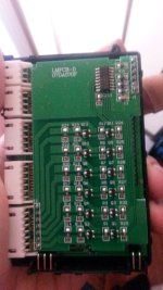
battery medic mod :P fast discharge

aaronlim said:
steveo said:
discharge current isn't measured ... but i was able to bring a 6s pack with cell votages ranging from 4.11v - 4.17v to a even 4.10v accross the board in a hour... very good if you ask me .. this was with 10ah pack..

Was this after the modding the resistors or just straight from the box?

Out of the box!!
 
Tried this, got back to stock medic.
Fact is, my nearly 2 year old hardcase lipo with over 300 cycles on them only needs balancing once every 30-50 cycles, and a single stock medic can do that during a single 8-hour work shift. I just need to reset a 90-minute timer after switching the medic from one jst plug to another.
Considering the new medics are faster and still somewhat accurate, and the pack is not huge in size, most should be fine with this.
 
https://www.facebook.com/photo.php?v=10200609996196058&set=vb.140675476024089&type=2&theater

Is going through that plug on the side a faster way to discharge packs? Will it also allow for faster balancing?
 
Greetings.....my first real post here after almost three years...you guys u'r doing a wonderful job.....

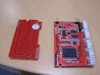
Here is an inside vew of the medic....its a non working unit..probably the dispaly is kaput.
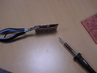
I managed to split it, using a small pliers pulling the two PCB's apart and heating up with my iron.

P1010001.JPG


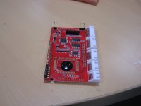
The "finished product"

P1010002.JPG


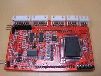
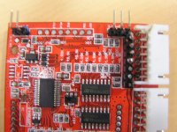
Detail of the board just under the LCD

P1010003.JPG

P101002.JPG

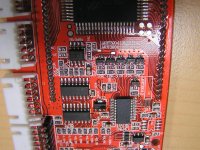
P1010012.JPG

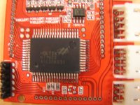
The main CPU (i thing)....

EDIt:Thats the RAM Mapping 32x8 LCD Controller

P1010015.JPG

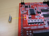
Any one can tell me what is this cylinder i found wondering around when i opened it....it was probably soldered at X1....????

P100013.JPG


Also ..do you guys thing it 'll be posible to replace the LCD in order to get it back working again...?? it used to be one of the good/accurate units

Thanks
 
That big IC is just the driver for the LCD display.

The loose part X1 is a crystal, providing the timing for the microcontroller.
The main "CPU" or micro controller will be the one next to the floating crystal.

Crystals aren't likely to fail. Looks like just physical damage caused it to rip off the pads and get loose. You can solder it back on - each leg will probably connect to a different (adjacent) micro controller pin and maybe a capacitor. It isn't polarised - can go back on in either direction.

I think you've got a good chance of fixing it if it's just the loose crystal. Not sure why you think the LCD is toast, it won't be replaceable unless you have another donor unit.

Greg
 
Gregory said:
That big IC is just the driver for the LCD display.

The loose part X1 is a crystal, providing the timing for the microcontroller.
The main "CPU" or micro controller will be the one next to the floating crystal.

Crystals aren't likely to fail. Looks like just physical damage caused it to rip off the pads and get loose. You can solder it back on - each leg will probably connect to a different (adjacent) micro controller pin and maybe a capacitor. It isn't polarised - can go back on in either direction.

I think you've got a good chance of fixing it if it's just the loose crystal. Not sure why you think the LCD is toast, it won't be replaceable unless you have another donor unit.

Greg


Thanks Gregory....I ll try to re-solder it ....its so tiny though...

Concerning the LCD i had read somewhere inside the forum that this things are very sensitive to heat.....probably i stacked one on top of the other, while still hot just after balancing .
I have another one not working, which i also spliced apart.
Interesting thing that it has completely different PCB layout...... though RED color both of them...no obvious damage what so ever

P01.JPG

 
BYqSXt8Z said:
so where would you put the resistors on this circuit board design to increase the discharge rate? I have 100 1ohm 5W resistors sitting around.

Simple toss that baby on discharge and look for the aray of resister with same value that make heat
 
drunkencat129 said:
BYqSXt8Z said:
so where would you put the resistors on this circuit board design to increase the discharge rate? I have 100 1ohm 5W resistors sitting around.

Simple toss that baby on discharge and look for the aray of resister with same value that make heat

hahahahaha! NICE! I love the simplicity of the solution. I'll report back for that board mod once I've done it.
 
the shunt resistors are the resistors paired together on the output of those little pchannel mosfets in that last picture. Q2,Q4,Q6...

can you read the number printed on them? they will be identical but that is where the charge is dissipated.

U1 in the upper right corner is what turns them on and off through that other set of mosfets on the right side. Q1,Q3,Q5....

i bet the reason it quit working was because the crystal separated from the solder pads.
 
Back
Top