BMS 3S 18650 charging

joz

100 µW
Joined
Apr 16, 2024
Messages
7
Location
Sombor
Hi!
I think this is a simple question for professionals but I can't figure it out by myself.
I connected 3 pieces of 18650 cells, BMS 3S 10A board, that indicator and the LED strip. It all works fine except one thing: batteries won't charge. Batteries and the BMS board are brand new. Batteries are refurbished though. But anyway. There was one black wire soldered to P- at one end, and I can't figure out where was the other end soldered, but I believe that's the reason why the batteries won't charge. Anyone with an idea please?
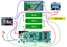
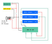
diagram-v7.png
 
Is the "12.6v, 2A" thing the charger input connector?

This looks like a single port BMS, so if it works during discharge, it should work for charging. I would plug in the charger and see if you get charger voltage on the rear side of the connector. The connector looks like it may have an internal switch that disconnects the load when you plug in the charger. The switch might be not making contact. If you measure voltage on the P+ and P- spots while plugging in the charger, you should see the voltage jump up a bit.
Yes, 12.6V 2A is the charger input connector. Exact voltage coming from the charger before I plug it in is 12.69V approximately.

The thing about charger connector is that before I removed the old batteries, I tried to plug in the charger and turn on the switch. Light came up. Without charger light was off. So the connector must be working, in my opinion.
Now after replacing the batteries and the BMS board, light is working after turning on the switch.

These are the voltages I measured few minutes ago:
Between P+ and P-, without charger, switch is off = 11.02V
Between B+ and B-, without charger, switch is off = 11.02V
Between P+ and P-, without charger, switch is ON = 10.8V
Between + and - of the charger before plugging it in = 12.69V
Between P+ and P-, with charger plugged in, switch is off = 11.02V

What would happen if I short connect with one wire P- and B- ?
 
I tried to short connect two "-" outputs from charger connector. Nothing changed so far. Voltage on P+ and P- is still the same and on the charger I have only the green LED indicator light on. Same as before. So, something else is the problem here.
 
Last edited:
What exactly is the charger itself? Is it actually a charger, or just a power supply? If it's just a typical PSU, they don't usually work as chargers, because when current is drawn over their limit, they turn off their output. A charger lowers it's voltage to nearly match that it's connected to, to limit the current to it's limit.

What are the actual cell voltages? If they aren't identical, the BMS may have a difference-limit to prevent cell damage that could lead to a fire when cells become aged or damaged and no longer work the same as each other. If any of them are too high or too low, outside whatever that specific BMS's HVC and LVC are, the BMS will turn off, again to protect the cells and you from a potential fire.

What are the cell chemistries? Different kinds charge to different voltages. Is the BMS the right kind for their chemistry? Is the charger's full voltage output correct for a full charge on that chemistry for that number of series cells?

What are the cell sources? There are a lot of scam 18650 sellers selling literal recycled garbage, sometimes re-wrapped as impossible-capacities, etc. It might not be charging because they may already be as full as they can get.
Thank you for answering.

The charger is a power supply of a simple LED strip. Ring light for photo studio. Old batteries had to be replaced. I thought it's a simple thing to do. So it was working the way it is right now. PSU and when the batteries are empty they plug in the Li-Ion charger and charge them up.

Here are the current cell voltages:
3.663V
3.670V
3.687V

About cell chemistry I don't have the information now. I'll try to find out and let you know if I get some info about it. But the seller said they should be around 4.2V when fully charged.

Cells are EVE ICR18650/26V 2.55Ah around 7.5A.
 
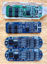
Forgot to mention and to show the picture of BMS 3S 10A boards I tried so far:
BMS 3S 10A boards_scaled_down.png

The one on top was the first one. I didn't get any output from it so I thought it is dead and I replaced it with the one in the middle. Then I learned it has to be activated. After activation the middle BMS behaved the same as the third one, which is in use at the moment. No charging. So it seems to me that the boards are not a problem.
 
Got everything working now properly. The first diagram was wrong. Here is the correct one:

WORKING_DIAGRAM_THIS_Screenshot_20240417_144527.png
 
What was wrong?
I had to switch the P- and the negative lead from LED strip on that charger input connector. You were right about the small NC switch inside the connector. It's not that it's not working but the diagram was wrong. I had no idea there is a NC switch there inside 😀 My friend helped me.
 
Back
Top