Bonanza "Bulldozer" Dual PhaseRunner AWD

Three Bears Loop Ride

ThreeBears.jpg


http://www.mapmyride.com/s/routes/view/bike-ride-map/california/martinez/3363949

18.6 miles, 1093 feet vertical gain, two climbs over 3% (both under 4%) when done clockwise. Looks from the profile like two steeper downhills, one is pretty long, looks like 10% for a mile. Would be quite a climb to do the course in reverse.

Route: Castro Ranch Road, Alhambra Valley Rd, Bear Creek Rd, San Pablo Dam Road. Circles along Briones and San Pablo Reservoirs. Not much traffic except on San Pablo Dam road, which has wide bike friendly margins along most of the route. Some pretty views and good photo ops on this route. There is a BART station in Orinda not too far from the loop.

This route is not far from my house, a mile or so, and is perhaps somewhat equivalent to my inbound work commute which has more vertical but is not quite as far. I have not ridden this route yet, though I've been on all these roads at some time or another. If things work out I'll try it by ebike soon.
 
Alan B said:
Another thing that would be fun to set up is Ham Radio APRS that sends GPS position reports. I suppose the Droid can do that too. Amazing how many of these current trendy tech things were invented years ago on Ham Radio.

N3RCG agrees with you. It's amazing how far we have come as well. Been a ham since I was 13, 33 now.
 
zombiess said:
Alan B said:
Another thing that would be fun to set up is Ham Radio APRS that sends GPS position reports. I suppose the Droid can do that too. Amazing how many of these current trendy tech things were invented years ago on Ham Radio.

N3RCG agrees with you. It's amazing how far we have come as well. Been a ham since I was 13, 33 now.

QSL es 73 de WB6ZQZ. Started at 13 myself, but that was a long time ago.


Ride Report

Mounted the battery back on the bike and went for a ride. Two miles to intersect the Three Bears Loop and the loop itself is almost 20 miles. Took it nice and easy, pedaled some, mostly ran 15-20 mph except for one max speed run, reached 27.3 or so on the level. Tried to moderately conserve energy, not pedal hard, be friendly to the pedal bikers and not zoom past them. The ride took 3/4 of my battery pack which uses six of the 6S 5AH Turnigy packs.

This is a nice loop. Much of it has wide margins. Not much traffic aside from San Pablo Dam Road, and that has wide margins for most of the ride portion. Reached almost 35 mph coasting on the downhill, that is about as high as I like to go on this bike. Passed quite a few pedalers going the other way, and a few going my direction. About a 500 foot climb in a mile they were going up as I was going down. The clockwise direction I took spaces out the climbing more, between 3-4 percent max.

A couple riders said I was cheating. One said he wanted some. One was laboring up a hill and said I was cheating as I passed him, so I asked him if he wanted a tow. We need a library of comebacks for the "cheating" thing. I'm trying to be very friendly to all the bikers, the last thing we need are more negative feelings. Over half the riders responded to me.

All in all, a great ride!!

From the Cycle Analyst

75.5 volts at start
23.4 miles total (the loop plus about 4 to/from my house)
7.4 amp hours used (of 10)
528 watt hours
22.5 watt hours per mile
60 amps max (this must be brief, I never see it, probably during block time)(CA limit is set to 50A)
66.0 volts min
1 hour 25 min
33.8 mph max (downhill)
16.4 mph average
 
DSC_5340.JPG


The handlebars are shaping up. From the left, Mountain Mirrycle mirror, Magura grip, Hayes hydraulic front brake, SRAM front shifter on Titec Micros barend, old bell/compass, Cycle Analyst, GoPro HD960 camera, rear shifter on barend, Tektro rear brake, Magura throttle. Everything uncluttered and within easy reach.

Note that the rear brake handle is Tektro (original on this bike) but the brake itself is XTR.

Photo from Three Bears Ride, San Pablo reservoir.

First battery parallel group recharged.

On the second group, upgraded to 30A 13.8V power supply, increased charge current from 2 amps to 6 amps (max for this charger). We will see how it works at this higher current.
 
Balance Charger Interface, RJ version

DSC_5320.JPG


Above is the board I built for each 6S group of parallel batteries. I have mounted three of these on my 18S battery pack. If you look closely at the photos above from today's ride you will see them at both ends and left of center on the battery pack. Not shown above is the PowerPole that mounts onto the tiewrap pad. The PowerPole cable carries the charge current and the RJ connector (on the right side above, epoxied to the board) carries the balance signals and current to the charger. The two are tiewrapped together both on the bike and on the charging cable so a mistake cannot easily be made by plugging the charge plug into one group and the balance plug into another.

The three groups of batteries in the pack I used today have all charged now. The last two at 6 amps (first was at 2 amps). So the RJ style setup is working OK. :D

They took 7.2 amp hours to charge and completed in about 90 minutes per group. This indicates that the Cycle Analyst is reading slightly high (7.4 amp hours). It is set for 2.2 milli ohms. That was the calibrated value I found for the previous 12 FET controller, and it has not been recalibrated yet. They are close enough I won't adjust it until I get a decent calibration setup ready.

RV Converter = Power Supply

The power supply I'm using might be of interest to some. It is an RV Converter - which is essentially a 13.8 volt power supply that is designed to operate across an RV battery in a trailer. These supplies are very rugged since it is required for handing the issues of charging a discharged deep cycle RV battery. They are often available at fairly low cost. This one is 30 Amps and was 25 bucks or so on eBay. Not quite as small or pretty as a Meanwell, but it is another option. I also have a 60 amp RV converter. Not as inexpensive, but occasionally available at a good price. Slightly used pulls from RV upgrades are often very inexpensive. Search the internet for RV Converter and check the specs. They are usually 12 volt output. These are a lot more suitable than an old PC power supply.
 
gtadmin said:
My setup is 4x 3S3P packs for the 12S3P motive battery, and a 3S2P pack for the lights etc. The plan is to parallel all balance leads per 3S pack, so that will be 5 lots of 4 wires going to the single DB25 allowing me balance charge each 3S pack separately, or as 2x 6S + 1x 3S. The balancing charge should be only once or twice a month based on how my 8S2P pack for the Aprilia is performing.

With a Meanwell set to 49.2V (4.10 per cell), I will be able to bulk charge the motive pack as a unit monitoring the cell voltages through the balance leads to 2x CellLog8s.

Once it's set up, there is no opportunity to mismatch wires as described by you. Well, that's the plan at the moment unless you see a problem or I find something next week that provides a better alternative.

I thought I might add another observation here regarding your battery pack plan. Let's count battery wires here:

4x3x2 = 24 motive wires
2x2 = 4 wires for lights etc

total 28 main power type battery wires, plus

14x4 = 56 balance wires

These all reduce when they get paralleled, but make for a lot of wires to deal with (and get perfectly right).

I think wire management is going to be a job. My pack has a lot of wires to manage, and it only has:

6x2 = 12 main wires (these larger wires create most of the clutter)
6x7 = 42 balance wires (these thin wires just plug into a PCB)

I'm quite happy with a PC board for the balance wiring, it really cuts down on the clutter and makes good fuses! :D

I thought about handling the battery current but that is hard to do on a low cost PCB. The conductors need to be thicker.
 
DSC_5328.JPG


Battery Pack Charging Setup

Here is a view of the battery pack with the new RJ45 balance charging connections. You can see the three white RJ jacks and the PowerPoles immediately to their left. The PowerPole carries the charge current, the RJ45 carries the balance currents. This has been in use for a couple of charge cycles at this point.

When first installed I had one problem, apparently a temporary short, but the boards performed as designed and the traces act like fairly low current fuses. So no big plasma ball formed, instead they just popped two traces. The event was not even noticeable.
 
Hi Alan,
Alan B said:
I thought I might add another observation here regarding your battery pack plan. Let's count battery wires here:

4x3x2 = 24 motive wires
2x2 = 4 wires for lights etc

total 28 main power type battery wires, plus

14x4 = 56 balance wires

These all reduce when they get paralleled, but make for a lot of wires to deal with (and get perfectly right).

I think wire management is going to be a job. My pack has a lot of wires to manage, and it only has:

6x2 = 12 main wires (these larger wires create most of the clutter)
6x7 = 42 balance wires (these thin wires just plug into a PCB)

I'm quite happy with a PC board for the balance wiring, it really cuts down on the clutter and makes good fuses! :D

I thought about handling the battery current but that is hard to do on a low cost PCB. The conductors need to be thicker.
A lot of wires to be sure! Consider the motive pack only though (and remember I'm 3P not 2P).

All the balancing wires end up as 16 when paralleled and treating each 3S pack in isolation, but if I really wanted to, this could be 13 (0V, 1S, 2S ... 12S). Ok, I'm not using PCBs to parallel but a prototyping board, but the same diff (and it has thicker traces :) ).

Ditto the "power" wires, they are paralleled using busbars rather than extra connectors and wire. So, ignoring the 2 wires (0V and 12S) going to the controller, there are 5 wires that need to go to the charge port (0V, 3S, 6S, 9S and 12S), this charge port being separate from the DB25. For bulk charging, only the 0V and 12S wires will be utilised. For balance charging, all 5 will be used if I'm balance charging 3S packs. If it proves that there is no difference in balancing 6S vs 3S (time wise) then only 3 will be utilised (0V, 6S and 12S). I have a feeling though that 3S balances in less than half the time that 6S does!

Does that make sense to you? Also, with my build the problem is not clutter, it's I have too much space to put the batteries in and support them properly.

Nice ride BTW, but I was trying to figure what all the green stuff was (until I realised it was vegetation :lol: - you can tell I live in the one of driest parts of the driest state of the driest continent on earth :shock: - but, just not this year)

Cheers mate,
GT
 
One of the rules I'm following is to not modify the battery wires and plugs as they come from the factory. So I'm stuck with at least connectors that match the batteries'. Mounting 4mm connectors to busbars in a way that can reach the batteries leads to wire (or long busbars). My busbars are the terminal strip. Anyway, it is amazing how quickly the wires add up. It will be interesting to see how it works out.

The balancing leads should be fused to protect the wires and batteries. So traces on the PCB make good fuses. I would not want too much current carrying capacity there. I am planning to beef up the traces a bit from the first board, but the interconnect should never approach the current handling of the balance wires we are protecting.

California is not usually this green, the weather has brought a lot more rain/warm cycles this spring than usual so things are really growing. Usually it dries out for the summer and everything turns brown. So this is a good year for green photos.

Charging Strategies

I've been giving some thought to where to go with charging strategies on this project. Now I have the 6S RJ balance setup, and soon I will probably switch to the 6S DB9 balance setup. This gets me going with a single 6S charger at home and work. Great start. But a bit slow to hook and charge three times. Speeding this up can be done in two ways. The easiest is to increase the charge current. I am at 6 amps now, and could go to 10 amps by making some adapters and using another charger I have a couple of. That might be worth doing. It still involves hooking up 3 times and pushing several buttons to get it charging. Could go even faster with higher current chargers. But they are not cheap and higher current has its disadvantages. For one thing the ending part of the charge is not at high current, so reducing the time becomes more difficult at a point.

So what other options make sense here. Bulk charging is a simple option that is commonly done. Alternating bulk charging with an occasional balance charge seems to be very popular and practical. A bulk charge on this pack takes 75 volts. The popular power supplies (Meanwells etc) don't seem to have an inexpensive model at that voltage. A pair of 36V units could be connected in series producing perhaps 8 amps of bulk charging. There are some problems with connecting supplies in series such as what happens when one shuts down, or when AC fails while charging...

Another interesting idea is to use three 24V supplies. With 6S charging jacks in place already it would be easy to avoid connecting the supplies in series. Each would go to one of the three charging jacks. A single six pole PowerPole block could be made that would do it all at once. The power supplies would float at the voltage of the series connected 6S packs. 24V 350 watt supplies can deliver almost 15 amps of charge current, so at 12 amps or so it would charge pretty fast. All three groups would be charging in parallel.

So what does it take to make a 24V bulk Lipo charger? One approach is to use a Meanwell 24V supply and a Fetchter current limiting board (per 6S block, so three of these for my setup). Set the voltage to the end of charge (4.2V per cell or so), and set the current limit as desired. The only other thing needed is auto-shutoff when the current drops low enough. I will get to that and other issues later.
 
Quick Test Ride

I'll probably regret it, but I took a "quick" test ride, 15 miles round trip out San Pablo Dam Road and back. Turned around at Bear Creek road. Full throttle except when going downhill more than a couple of percent. Pedaled hard on the uphills to keep the speed up, averaged 24 mph and 33 watt hours per mile. Right about 7.5 amp hours for the 15 miles. Not many cyclists out at this time, but those going my way got passed soundly at about 28 mph. A yellow enclosed low recumbent was going the other way both passes, we waved.

This 6x10 motor at 70 volts does nicely at 25-28 mph. Nothing got more than barely warm. I'll need more battery if I'm going to do that very much...

Hopefully I won't feel too bad from pedaling too hard. Not used to that.

Edit - got sick, probably not from pedaling, but I was coming down with something when I took this ride...
 
New 6S Lipo Charge Interface PCBoards

I designed and ordered a set of PC boards that use DB-9 connectors for the charger interface, and JST-XH connectors for the Lipo batteries. The basic design was shown a couple of days ago in this thread. It has been refined. Essentially the PowerPole will carry the charge current and the DB9 will carry the balance current. Traces have been beefed up but should still open long before the wiring and eliminate any plasma events even if things are plugged in wrong on the balance side. The PowerPoles go straight to the batteries via wires anchored to the board with tie wraps, no fuse yet, so some potential there for problems. In my case only one PowerPole charging plug exists on my charge station so plugging two should be a non risk. When I do get to the point of having more than one PowerPole and charger they will be floating so it won't matter which they plug into, as long as the balance lines go with the charge lines. As before, they will be tie-wrapped together so they won't reach far enough to get into trouble.

I used the ExpressPCB circuit board software and their MiniBoard service which provides 3 each 2.5 by 3.8 inch boards in a day or two plus shipping time - generally less than a week total. Cost is $51 plus tax and shipping for these three boards. The software is free and easy to use. Push a button and it sends the file over the internet to them. The boards are professional quality double sided with plated through holes and solder reflow. There is no solder mask or silkscreen at this price. They offer other board services as well. The boards are manufactured in the USA. Not sure where the materials come from.

edit - note that Fetchter and Goodrum uses ExpressPCB for their BMS boards as well! (Listen to ES podcast #11 to hearm them discuss their BMS design experiences).

What I generally do is lay out several boards within the Miniboard and then cut them apart. In this case I will get three battery interface boards and three charger interface boards for about $60. It is much faster than BatchPCB which takes about 3 to 4 weeks. The cost per unit area is about the same, but BatchPCB has solder mask and silkscreen and makes boards most any size. Each service has their pros and cons.

It is so easy to lay out boards with ExpressPCB I'm surprised a lot more folks don't do it.
 
Parts are on order from Mouser for the DB9 adapters, and a few other things like a keyswitch.

Completed charging the pack again. RJ balance interface working well. Used my second Turnigy 8150 charger. Current calibration is quite different from the first unit (amp hours). Not nice. 7.0 vs 7.4 amp hours.
 
Range Anxiety

I would like to get another 10AH on the bike, at least for some trips. I don't want it on the rear racks. I could barely fit another 5AH in the triangle, and maybe I should do that. But it will be tight.

So what about putting a pack forward of the cranks, like a lot of motorcycles do and PaulD did on his racing bike?

There is 8" from chainrings to front tire. A 2x3 array of 6S 5AH Turnigy takes 6" wide by 6" high by 4" deep, so they could be placed vertically to leave room for wiring at the top. The box would have to be fairly thin to avoid adding bulk. Perhaps sheet aluminum.

Tricky to support them there mechanically. Perhaps some struts to the chainstays and the down tube. Would be nice to make the pack removable.

To connect them could use a pair of cables. One four conductor brings up the 0, 25, 50 and 75 volt taps. For the other use a DB25 to bring all the balance taps up and parallel them with the topside pack (7x3 conductors). If I get a JST crimper I could make the DB25 cabling plug right into my boards for a clean install... The range extender pack would have its own set of three DB9/JST boards so it could be balanced off-bike. When on-bike they would be charged through the connectors on the main pack. So no extra complications. Just takes longer to charge. The aux pack would have a little greater impedance to the controller. Have to see if this is enough to be important. Could balance it if necessary.

Note that Sparkfun has an inexpensive JST crimper that may work.
 
ExpressPCB has already shipped my new PC boards that I designed friday and ordered sunday. Very nice.

Today I was cruising the McMaster Carr site looking for better materials to support my batteries. The red oak boards are light but they are bending a bit width-wise from the force of the saddle clamps. I was thinking of aluminum or fiberglass. I found some fiberglass U channel that is 4-3/4" wide, 3/16" thick and 1-5/8" high. Might make a good material for the lower battery box!

So I ordered some fiberglass and aluminum strips to see what will work best for the current battery support upgrade. One thing I want to change is to make the saddle blocks tight on the downtube even when the battery and support is not installed. It is difficult to get the battery and saddle blocks in the right place at the same time, having the saddle blocks in firmly will make it much easier to drop the batteries in over the extra length of threaded bolt. Not quite plug-in but close.
 
Next Battery Step

After reviewing things I have decided my next battery upgrade will be to add 3 packs to the triangle and bring it up to a kilowatt hour, a 50 percent increase (weight will go from 63 to 70 pounds). At the same time (or before) I will upgrade the pack mounts and charging interface boards. Adding another 10AH below the downtube will be reserved for later. The batteries are now on order. Most of the rest is already enroute. Stepwise Refinement. Get something working and then improve it.

The system is now good enough that I could meet my first requirement - commute to work. It is not weatherproof yet, and I don't have all the riding gear yet, but in good weather I could do it now. I would probably have attempted it today except my temperature is 101F. So I'm stuck home reading ES. How terrible.

Power Control Throttle

I am tempted to hook up the Cycle Analyst for Battery Current Throttle control. In this mode the throttle provides a signal that the CA uses to control the battery current from zero to your full current setting. So this makes it a "power level" control. The default throttle control on these controllers is a "pwm control" which equates to "motor voltage" which means "motor speed". You notice when you vary the throttle a little the motor power varies significantly from no power to full power as you pass through the "current speed". This makes the throttle twitchy and un-natural if you are accustomed to ICE throttles. Many folks have talked about doing this but as far as I can tell few have done so. The feature is built into late model Cycle Analysts if you bother to connect it up. It requires bringing the throttle into the CA and back out to the controller. The normal CA throttle interface is for limiting, and is not adequate for this. So wiring changes are needed. Review your CA manual for details. It is near the back of the manual. Has anyone tested this feature???
 
Might try something like I made for more batteries. I still need to make one more for the other side. Mine are just 20 ga. steel. Your bike looks great. Really like the "dash".
 

Attachments

  • a bat mounted.JPG
    a bat mounted.JPG
    39.6 KB · Views: 2,079
Thanks for your comments!

Looks like substantial protection and fits the batteries well. How wide do you feel you can go before it bothers your knees while pedaling? So far I've stayed pretty narrow.

I probably need to get set up to work with sheet metal. Used to have a cheapo brake, but don't know where it went. More Tools! :D

Need to upgrade my Dash with a large screen Cycle Analyst soon! I bought mine not that long ago but they must have had an older model still on the shelf and I got it.
 
I just got a Turnigy watt meter the other day . I love it. Much smaller than the multimeter I had taped on the handlebars :) This is small enough to velcro on the stem. It is sure handy. I run my 6x10 in a 20" rear and I am getting around 45 A peaks everytime I ride but only for like a second at a time. If I really try I can manage 2900W and 55 A but usually it is more like 12-1500 W so unless I start doing some serious offroading hopefully I am safe. I use it mostly to keep tabs on voltage. I back off as soon as I hit 56 V @ 15s

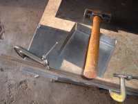
I made the boxes big enough for 4x 5s packs on the tall edge with a little room for padding. I plan on making one for the other side and then I am going to see if I can make an mx style seat by wrapping some metal around my seat and extending it forward and using lifejacket foam and material to cover it. If I can make it look OK. I even thought about connecting it to my battery pods somehow to give me a "gas tank" like point for leverage when dirt riding. Not sure how I will pull this off and make it look good and be sturdy enough though. As far as tools, I used some angle iron and clamped the metal to the edge of some OSB and hammered it into shape. :lol: Crude, but I took my time and it came out nice and square. Yes, My hammer is slightly oversize but my ballpeen is too small. 3 pounds is just right for 20 ga. steel if you're careful :mrgreen:
 

Attachments

  • a batbox.JPG
    a batbox.JPG
    35.5 KB · Views: 1,933
Great job, and leads right into something I've been thinking about! Shucks, now I'm looking at 3 in 1 sheet metal machines (Grizzly.com).

Motor Temperature Monitoring

Hubmotors get hot, and it would really help to have a good temperature gauge on the copper windings in the stator. Most semiconductor temperature sensors are not capable of handling high motor temperatures, so a good choice is a thermocouple. A sensor that can handle 200C is about right, and various folks operate up to 160C or maybe a bit higher. For racing or hill climbing it is important to have this data available (even if you ignore it while actually racing). For commuting or having fun it can be the difference between destroying a motor, taking a break or slowing down.

Sparkfun is a good place to look for ideas, and they have K thermocouples and a couple of chips to interface them. These devices can withstand high temperatures, beyond most insulating materials so the limit becomes the insulator. Glass fiber braid insulated units are good up to about 480C. That will more than meet our needs. Thermocouples produce millivolt signals (small) and need "cold junction compensation" since they really measure temperature differences. Sparkfun carries two interface chips for "K" thermocouples, one produces an analog voltage output (AD-595-AQ) and the other digitizes the temperature for readout by a microprocessor (MAX6675). There are examples of builds on the web using the MAX6675 and a micro and LCD to display the temperature. This micro could also be programmed to limit the throttle setting as the motor heated up to protect the motor without a display being required. It could warn with an LED or buzzer as high temperature is reached, and a few degrees higher start shutting down the throttle.

Many multimeters have thermocouple inputs, so you could strap one of these meters on the handlebars for testing and remove it later. The key requirement is to place the thermocouple into the motor. Often thermocouples are epoxied to or in the material to measure. Thin epoxy won't delay the reading too much. I would do this at the same time the phase wires were being upgraded. So next time you have your motor apart, make sure to install a thermocouple for future use! Perhaps someday we can even get the manufacturers to do this right at the factory.
 
That would be cool :roll: pun intended.. The motor I am using is one of Methods from his "Old Crusty Hub" sale. I had to clean the windings on one phase and resolder them and 2 of the halls were loose. 3M epoxy took care of that. I also drilled 3/8" cooling holes, actually I think they are 1/2" while I had it apart. Once I get more funds foe batteries and a beefier controller I will probably take it apart again for just the mods you mention. Right now with only 5 ah I can't torture it for too long at one time. Probably a good thing. I am running an old 22a 9 fet Infineon with 63 v caps at 63 v hot. :shock: I added a wire to the shunt and enabled regen. Although regen doesn't work till I drop below 60 v. Which doesn't take too long :mrgreen: Here is another pic so you can see how wide the box is. I'll use Photobucket this time for full res. As you can see it isn't any wider than my front forks. Well not much ..
adash.jpg
 
Probably about 2"+ for the box, plus another plus the top tube is probably 1.5" so total around six inches.

On my bike there is about 5.5" between the cranks, so I figured I would try to stay within 5" width for the whole triangle. Still need to stay clear of the chainring area. as they intrude on that space some. Not sure this 5" is significant but at some point it gets hard to pedal. 6" is probably ok. Do you bump the box at all while pedaling?
 
No bumping. Although I do have the pedals and chain off right now till I get some bmx cranks. I ran it with pedals but they were just too close to the ground for me as I now have 20" wheels all around. I built this mostly for dirt. The box is up high enough that it doesn't bother pedaling at all though. And if you look back at the pic it could be narrower. I made it where the batts would fit 90 deg. from their current position which is taller. The way they are in there now it is really loose . If you made the box smooth then a good snug fit would be fine. The only place I have a rough spot is where the screws mount it to the frame. I riveted the box together from the inside out so they are smooth on the inside. I just need to come up with a clever way to mount it. I guess I could dimple the box to recess the screws but then it would not fit flush to the frame :x
 
Back
Top