Bonanza "Bulldozer" Dual PhaseRunner AWD

Hi Alan,

Very nice. Looks like it can climb very well indeed.

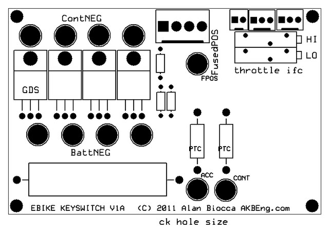
Have been using PCBExpress for years, and they have a great system. If others on the forum want the boards you could share your files -as you mentioned the software is a simple download.

Be sure to keep an eye on the front stay for your rack.

Looks great!
 
Alan B said:
Hi Adrian,

My charger is reaching 6.0 amps (which is about all it can do on 6S), so the impedance of the charge lines is not an issue. The charger is the Turnigy Accucel 8150. So far that's the only charger I've tried.

I did change the wires from about 4 feet long to about 7 to 8 feet in this last upgrade, and they are 18 gauge red/black Radio Shack speaker wire. This reached 6.0 amps during my charging test.

Depending on the charger, the results might be different. Which charger, and what length of what gauge wire did you use?

18 guage? :shock: I am was talking about seeing a difference between 10 & 12 guage, with only 1-2 foot lengths.

I was also using the Turnigy Accucel 8150. I too reached 6 Amps at the start of charging, but noticed it went into CV early with with crappy leads. Try putting a volt meter across red & black at where the wires exit the charger (note the voltage) then repeat for where the charge leads plug in to the battery. Mine were quite different.

The end result is that the charger thinks it is putting out the required constant voltage, but the battery can be seeing a lower voltage. Therefore your whole charging process is slower than it could be.

Here is an online calculator that helps quantify the effect.
http://www.stealth316.com/2-wire-resistance.htm
 
Interesting. My observation of the Turnigy 8150 is that it stays at 6 amps until the terminal voltage reads 25.2, and then it drops. Now I have not verified any readings yet, but I would expect that voltage is being read from the balance leads which are not subject to the voltage drops from the current in the charging lines. So the charger's output would be slightly higher to compensate for the leads.

So if this charger is incorrectly reading the voltage from the charging leads then their drop would be important, and would slow the last part of the charge cycle.

One easy way to tell is to put a voltmeter across the charger output and see if the output voltage agrees with the reading on the display, or is higher from the lead drop.

At 6.3 ohms per 1,000 feet, assuming I have 16 feet of total wire the resistance would be 101 milli-ohms. At 6 amps this would drop 600 millivolts or 0.6 volts. That should be easy to measure.

Note also that connections might play a part. I have pretty solid connections on this circuit. Also the internal impedance of the batteries matter in this. It would be easy to beef the wiring up, if it is necessary. Thanks for the comment and I'll check it.

My observation thus far is that it stays on 6.0 amps for most of the cycle, so it looks "normal".
 
Would be interested to see if it ups the voltage on the main leads based on what it measures on the balance leads. But I wouldn't hold my breath. These are pretty cheap chargers. I did this testing ages ago, so can't remember if I looked at that. Easy to test though.

For me it just convinced me to go for as short, and fat power cables for charging as practical. 10 guage is what I had at hand, and still use.
 
That's what I expect it would do. It is a pretty simple microprocessor controlled setup, reading the balance lines and controlling the charger PWM. If they didn't do that it would be a major mistake in their software. Would not cost any more to do it right, and it is worthwhile to get the software right when they're making lots of copies. But that is no guarantee they did!
 
eBike Keyswitch

Well, I've been working on a printed circuit board for the keyswitch. Pretty much along the lines of the schematic posted here a few articles back.

The basic layout is done. Quad parallel FETs should handle the current. You can always mount fewer FETs. Need to sort out the connector details and get the hole sizes right, and figure out what to put on the rest of the pc board space. I already have the Magura interface on it - need a better place for those parts than they have on my bike now.

So what else would be handy on this board? Maybe a motor temperature interface?

Other suggestions?
 
Alan, do I understand from your photos that you charge 3 packs of 6s in parallel at a time? And that you have 3 sets of 3P6S to charge? And further that you have one charger, so you charge the entire pack manually in series?

I love what you're doing and after my own battery problems I'm considering the move to LiPo, likely modeling your setup. My concern is that I use my bike every day to commute so I'd hate to have to spend so much manual effort charging every day. I love the way (if I understand correctly) you charge 3P at once. So elegant. I might head over the bridge for a visit to cheat off you and get some boards made myself.

(I'm looking at building a 20S4P pack of Turnigy nano 5Ah 10S packs for roughly 75v20Ah)
 
Hi Ryan. I can charge all three "groups" at once if I have three 6S chargers and separate power supplies. Which is certainly do-able.

If I were to break the series connection between the "Groups" I could charge them all in parallel. So far I'm not doing that.

I plan to commute with it, so I may get tired of plugging in one charger three times, though it doesn't take a lot of effort. This is just the first step in a journey to the final system.

One other way to charge this pack is with two 36V meanwells in series and a current limiter board. Bulk charging. If I were to alternate between balance charging and bulk charging, doing one at work and one at home, that would keep things balanced pretty well.
 
Keyswitch Control Board

ebike-keyswitch-v1a.jpg


Here is the layout at the moment, traces are not shown. The left 2/3 of the board is the keyswitch circuit, the upper right corner is the Magura throttle interface. The Magura interface provides variable resistors to adjust the range for the full rotation of the throttle, and it has a connector for remote clamping of the throttle such as used by LVC boards. Shorting the pins will take the throttle to zero.

There is still room for something in the lower right.

Not everything is sized correctly, but most of it is close. Not sure I like those connectors at the top for the keyswitch and throttle, they were library Molex parts. So need to think about what to use there.

The current carrying wires are quad #12 wires which equals a number six. Soldering a number six wire to this board seems unlikely, but a few #12's would be manageable.

The keyswitch needs two contact closures, one for precharge, and a separate one for operate. They must be two separate poles, one operates at pack negative and one at pack positive.
 
Motor Temperature

So let's assume for a moment that I put a motor temperature sensor on the board. What to do with the data? A display is nice but a lot of trouble. What is really essential here? Perhaps the motor temperature should do something to the throttle. I already have the throttle on this board, so perhaps that's the way to handle it.

What would the algorithm be? Turn the throttle off for a short time every little while when the temperature exceeds one value. The higher it gets, the longer it stays off each cycle. Finally, it stays off altogether when the high limit is reached. Perhaps have jumper to disable all this when needed.

One of the difficult things to do is get 5 volts to power the circuit. Might be able to borrow that from the controller's throttle power. Hmmm.
 
Can you have it just pull the throttle signal down, like a CA throttle override.

Temp < T1: Throttle left alone
T1 < Temp < T2: Throttle is progressively limitted to less than full throttle.
T2 < Temp : Throttle Off.
 
adrian_sm said:
Can you have it just pull the throttle signal down, like a CA throttle override.

Temp < T1: Throttle left alone
T1 < Temp < T2: Throttle is progressively limitted to less than full throttle.
T2 < Temp : Throttle Off.

That is possible, too. It would not be as clear to the rider, though. But with software not hard to do. It would require slightly more complicated hardware. A few more parts.
 
Sorry to jump in to this thread late, but I have been out of the loop a while. I have just started playing around with a 6x10 for my son's 26' MTB so we can ride together. This is my first hub motor. I am looking at batteries and controllers. Forgive my battery ignorance.

I think it is true that I can't simply get two 24v lithium chemistry packs and put them together in series without somehow tying the charging and BMS functions for the two packs together. (Does the BMS effect BOTH charging and discharging?) The battery on my bike is a pouch cell 36v LiPO4, but might do something different on this one. I have heard a lot about the batteries for the RC market and might go that way, if I can figure it out. I like the simplicity of the one plug for charging, if that can be done.
 
I started (earlier in this thread) with a pair of 6S 5AH Lipos in series. This can be charged with a 12-14S charger, and there are a couple of those out there. Wire up all the balance leads to a DB25 for a two-plug charging setup. The second plug could be a PowerPole for the charging current. The DB25 cable wires are too small a gauge for the charging current, but are fine for cell balancing.

When you add 6S packs, just parallel the power and balance leads for each of the two 6S banks. Never mix up leads from the two banks or BANG.

I find that 18S works well on the 9C 6x10. That is what I am using now, and since there are no 18S chargers I'm using a 6S charger and plugging in 3 times.

Some BMS's affect both charge and discharge, depends on how they are configured. At the moment my "BMS" is watching the Cycle Analyst amp-hour and voltage for end of charge, and using the RC balance chargers for the management of the charge cycle. I will be adding Low Voltage Cutoff to the bike and this will control the throttle for simplicity.
 
I would personally enjoy a buzzer and or light for overheat. Another approach would be a two step throttle clamp. Limited current available at the first threshold followed by no throttle for the second higher threshold.
Cars used to have various cut offs so the engine stopped before it was damaged. Later it was decided that stopping the motor was dangerous and confusing. Modern cars always have a light or buzzer but no cut off.
I remember some of the early Vespa sized e scooters had a series of safety interlocks including one where the scooter would not run with the kick stand down. This system caused more harm than good and resulted in a bunch of unsatisfied customers.
I think blinking light and or buzzer would work well and add little complexity and cost. Whatever you decide to do I would buy one of these circuits when they are available.
 
mr.electric said:
I would personally enjoy a buzzer and or light for overheat. Another approach would be a two step throttle clamp. Limited current available at the first threshold followed by no throttle for the second higher threshold.
Cars used to have various cut offs so the engine stopped before it was damaged. Later it was decided that stopping the motor was dangerous and confusing. Modern cars always have a light or buzzer but no cut off.
I remember some of the early Vespa sized e scooters had a series of safety interlocks including one where the scooter would not run with the kick stand down. This system caused more harm than good and resulted in a bunch of unsatisfied customers.
I think blinking light and or buzzer would work well and add little complexity and cost. Whatever you decide to do I would buy one of these circuits when they are available.

Thanks for the input. I may have room for a buzzer on this board, I'll look into it.

One trick with the throttle I've been thinking about is to "blip" it to send a message, just a quick interruption to let you know that something is wrong. Not enough to stop you, but enough to be unmistakeable. A buzzer might be good too!
 
eBike riding Gloves

Went glove shopping a couple of times, didn't really like the regular bike gloves. The other day stopped by Cycle Gear and looked at motorcycle gloves. Found a pair I like, Sedici Corsa gloves.

These are not insulated, but have good protection on palms and knuckles. The feel of the grips through them is nice. They have some blue on the back, and some light tan on the palm so if you do give a hand signal they are not "invisible black gloves". Especially the palm. If you ever needed to smack something they would give pretty good protection. They may be too warm for some riding, but commuting tends to avoid the heat of the day so I suspect they will not be too hot. Cold weather would probably require warmer gloves or liners could extend the season for these.

DSC_5420.JPG
 
Keyswitch Current Surges

Today I fired up LTSpice, a free electronics modelling program. With some typical values I observed 1200 amp surges when the controller was connected to the battery. :shock: Clearly this is hard on the connector or switch, or the FET in this design. By making adjustments to the network feeding the FET gate I was able to drop this to 18 amps peak. Even in this slow turn-on configuration the FET was fully turned on in well under 100 milliseconds. :idea: Under these conditions the resistive precharge is not required. I modified the PC board design to reflect this. During the precharge (switch position two) the FETs are turned on, but the controller and secondary loads are not; in the operate position both the FETs and the controller as well as the secondary loads are energized.

The remaining question is how much heat is deposited into the FETs during this linear turn-on period. The duration of the current spike is about 0.01 seconds, and at 18 amps the worst case power dissipation would be half the voltage in the FETs, or 18 * 75 / 2 which is about 700 watts. :shock: However the duration of this current is less than 0.01 seconds so the total energy is about 7 watt seconds. In fact due to the shape of this pulse the actual dissipation is closer to half of that value. :)
 
Keyswitch Positions

There are three positions on my keyswitch. Position one is off/key removal. The question is how to best use the other two:

Set 1:
2) precharge
3) operate (precharge is automatic)

OR

Set 2:
2) accessory only (motor not powered)
3) operate (precharge is automatic)

I wonder if the second set is more useful. This would send power to the accessory output, and the controller logic (since this powers the Cycle Analyst), but not the main power to the controller, so the motor could not run. This way you could pedal the bike and see speed, etc, but the throttle would be inactive.

This would be analagous to the keyswitch in most vehicles, less the "start" momentary position.
 
I really like the keyswitch module idea. I too hate unplugging things over and over, but I know better than to leave things plugged in for a period of time :lol:

I like option two since the precharge is automatic for running anyway. Maybe have headlights and the CA turn on with it.
 
Well, I was making changes to the design to make it have position #2 Accessory power when I remembered why this won't work. The power FETs are in the negative lead, so connecting the positive to the accessories won't help. I think trying to switch the accessories negative leads is likely to lead to other problems. Most things don't expect switching in the negative lead.

So perhaps the best way to do this is to power the controller main and the accessories from position #2 and the controller logic from position #3. The problem with this is the Cycle Analyst DP is usually powered by the controller logic. So it won't come on in position #2 unless rewired.

In other news the Cycle Analysts are still on delay but may ship in another week or two.
 
Keyswitch FET Heat

did some calcs for IRFB4110's at 50 amps DC (assuming equal current division, P = (I/N)^2*R):

1 FET 11.25 watts
2 FETs in parallel 2.8 watts each
3 FETs in parallel 1.25 watts each
4 FETs in parallel 0.70 watts each

So at the 50 amp level 3 FETs with very minimal heatsink would do, four is excellent! (my board layout has four) :D
 
Back
Top