building the BESC - 100V, 400A motor controller [NOT RECOMMENDED]

Status
Not open for further replies.
Hi together,

a colleague and I plan to use the Besc G2 controller for our builds!
@owhite, @galp and all other contributors - thank you so much for sharing your knowledge.

A few questions appeared to me while reading the thread
1) did someone build a running board with the v1.1 files?
2) @owhite you worked on a modified version of the board (I think based on Galp's v1.0?), did you finish this board?
3) Could someone support me / or share some useful links and tipps for PCBA using KiCad? (I'd like to order via PCBway, too.)

Looking forward to your responses.
rl
 
1) did someone build a running board with the v1.1 files?
I am not aware if anyone has used it. I asked Galp quite some time ago but didnt hear anything.

2) @owhite you worked on a modified version of the board (I think based on Galp's v1.0?), did you finish this board?
I made two modifications of 1.0 -- one had some flaw in it that resulted in it failing.

The other was described in this post. Be advised, the zip file I posted have some problems, and I owe the world an updated file. That post also gave my tips for creating PCBA files and if you have more questions I'm happy to help.

owen
 
Hi guys, sorry for offtopic but anyone can sell me 1 pcb (or exchange for some electronics, someone were needed stm32- i have spare) of 1.1 or 1.0? I dont want to order 5.
 
Hello Everyone,

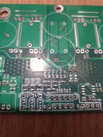
This post is to update people on my PCBA experience with using Galp's v1.0 board.

It was posted on endless-sphere here:
https://endless-sphere.com/forums/viewtopic.php?f=2&t=109266&start=75#p1656363
The silk for that OLD file was labeled "V2.0, May 2021, OW"

Those boards were assembled, but some things were changed thanks to PCBway finding some errors. The notes below show a combination of what was done to create may2021, AND how you had to fix the board that board to work.

I am now posting the Nov2021 version, that represents an update of everything. Updated files are included in the zip file. The attached file when unzipped includes a readme with a subset of these instructions. Found in: README.txt

The resulting zip file may be found HERE

The silk for that NEW file is labeled "V2.1, Nov 2021, OW"
What was done to create these files:

This board started with Galp's v1.0
Total set of known changesModifications to schematic and eeschema:
-updated the silk to "V2.1, Nov 2021"
-changed pins of the crystal (to connect circuit to 1 & 3)
-tied pin 2 of crystal to ground
-changed crystal to (ECS-80-18-30B-AGN-TR)
-trace to pin 2 of crystal to ground
-changed footprint of crystal
-removed U7, fixed traces
-minor changes to silk
-added "MANUFACTURER", "PART", "SMD/TH" into symbol editor, populated all those fields
dumped all the parts into single column, cut and pasted into mouser BOM maker
cut and pasted all the part manufacturers from mouser spreadsheet into the symbol editor
edited the SMD/TH column
-the original part for USBLC6-2P6 was wrong
-the foot print for:
C34-C39, C54, C62, C64, C76, C78, C83, C89, C95, C99, C102, C103, C106, C109
should be 0603, changed the part to: 810-C1608X8L0J225K08
-the part number assigned to C4,C5,C6,C7,C8,C9,C13,C14,C15,C65,C66,C67,C104 were wrong, and needed to be 270p
used: Mouser #:80-C0603C271J5G
-added part numbers for the LEDs
-TAJD107M016RNJ was too large (note "D" in TAJD)
Changed to TAJC107M016RNJ (note "C" in TAJC)
-PCBway wondered if R77,R78 part RC0603FR-1324R9L, value is 24.9R ok. it is okay.
-TH1 (the termister) of may2021 was wrong.
changed to mouser #81-NCU18XH103F6SRB

The directory: "T-K124W15822A pictures" shows some pictures that were part of the emails from PCBWay
The spreadsheet "t-k124w15822a_response.xlsx" was sent by PCBway to confirm some parts. It also contains prices.

Hey, speaking of price, how much did this cost?
$116 for 10 PCBs
$1196 for 5 assembled boards
that does not include the cost of throughput parts.

==============================
==============================

MAKING THE BOM FROM KICAD EESCHEMA
For MacOS,
copy my_BOM2csv.xsl plugin to here:
/Applications/KiCad/kicad.app/Contents/SharedSupport/plugins

Got to Tools->Generate Bill of Materials

Load up your custom script

Be sure to change:

"%O"
to
"%O.csv"

Manually:
-touch up the column headings if needed (in my case there were extras)
-sort on SMD/TH to find rows to remove
-save as excel file
-remove csv old files

total parts: 226
------------------------------
MAKING THE CENTROID FILE FROM PCBNEW:
File --> fabrication outputs --> footprint position file
Select: CSV, millimeters, single file for board
Select: "Include footprints with SMD pad even if not marked Surface Mount"
(gets R31, R32, R33)
Open the resulting file, do these steps manually

-You have to remove some stray parts
remove all refs beginning with J, FED
-Rearrange columns so the fits the headings in the next step:

- add:
"*RefDes<TAB>MidX (mm)<TAB>MidY (mm)<TAB>Package<TAB>Rotation<TAB>Top/Bottom<TAB>Val"
to the top

- save as excel file
- remove csv file

total parts: 226
------------------------------=
PCBway wants all the components could be clustered on to one line

Use bom2grouped_csv from eeschema
set output to %O.csv"
Import into excel
Look at column SMD/TH --> Sort on SMD/TH
Remove all non-SMD parts

Total lines: 53

Perform a sum on column B:
Total parts: 226

------------------------------=
create gerber files.

in PCBnew:
File --> plot

Use the gerber settings as shown in PCBA/GERBER_SETTINGS.png

Hit Generate Drill Files...
Use the gerber settings as shown in PCBA/GERBER_SETTINGS.png

==============================
==============================

NOTE: when I report in the notes above that something was "wrong" that does not mean Galp's original design had a problem. It may very well have been introduced when I made modifications to his file in order to create a BOM. I am not saying his original schematic or PCB had errors.
 
Hey guys. I endup ordering BESC v1.1 PCB myself. I also ordered SMD service, so most of tiny passive elements already pre-soldered. Now i have 5 boards on my hand and i dont need that much. I can sell each for 12USD (as much as i paid). It also fits in standard letter so shippind anywhere in the world should be just few extra bucks. PMs welcome.
 

Attachments

  • photo5350315300240866560.jpg
    photo5350315300240866560.jpg
    168.7 KB · Views: 965
[ALL SOLD] Hello guys, as I changed my plans, if anyone is interested, i have a lot of new components bought on Mouser and Farnell, ready for sale, including mosfets, capacitors and a STM32. Feel free to PM me :)
 
Very interesting project! Would this board be able to handle a 24S lipo battery (100.8V fully charged)

or would it go poof?
 
Very interesting project! Would this board be able to handle a 24S lipo battery (100.8V fully charged)

or would it go poof?

I run 24S, and yes it works, and yes some times it fails. I dont want to discourage you, I still use my boards and I enjoy having the control over the whole system. I would suggest it sort of involves if you like working with electronics. I will also say there are very few alternatives to run at the 24S range. Some other person on ES might be able to suggest another controller but because I really like VESCs it is still my preference.

One SERIOUS concern are supply chain issues. Be sure to factor in how long it might take to get the microcontrollers. My last order to have them made by PCBA was two months.
 
Greetings friends. There was a problem with assembling a new firmware 5.3 for besc g2, can anyone show what the problem is?
maybe someone has a built firmware for the new version, I will be very grateful


https://imgur.com/a/BYIf7R0
 
Desper said:
Greetings friends. There was a problem with assembling a new firmware 5.3 for besc g2, can anyone show what the problem is?
maybe someone has a built firmware for the new version, I will be very grateful

Sorry I dont know the answer but since that's a problem with VESC code you could ask everyone over in the VESC forum
 
Hi guys,
I might have made a mistake when setting up my besc. @Louiss was so friendly to send me his Firmware v6.02 and I completed the setup with motor detection and everything was alright. My hub motor was running and I called it a success. One day later I tried running the besc with another power source and therefore I re-ran everything. Unfortunatelly this time with the phase filters on because I didn't pay attention and just loaded the standard config o_O. If I run the auto-setup now with the firmware v6.02 it only detects nonsense with unrealistically high inductance and resistance values (Motor also not turning and just doing some weird stuff). However, if I flash the older firmware provided from Galp, everything seems to work just fine, only the current readings are a little off but the motor spins just fine and the detection work as intended.
Do you guys have any idea what could be the issue here, because clearly something broke. There is no visible damage and also no magic smoke escaped.

Thanks, Max
 
Hi guys,
meanwhile, I could narrow down the problem to the current measurement. It seems like the measurement itself is correct, it just has a posivitve DC-Offset for Phase 1 and Phase 2 and a negative Offset for Phase 3. By applying the correct offsets in software, the system seems to work again. Nevertheless, somewhere has to be a problem in hardware. To my understanding, the fault can occur in 3 different places.

1. The microcontroller itself (maybe some problems with the ADC).
2. the shunt opamps.
3. the gate drivers (because of the low side current measurement).

What do you think, does this sound plausible to you?

Thanks, Max
Max, sorry this is not going to be very helpful, but tbh VESC motor detection is not very good. If you remember your motor values when the ESC was working well you could try to type those into VESCtool manually. The other thing that worries me is for any ESC, if you run some of the components out of spec it is not uncommon to experience the type of problems you're having -- the chip does not necessarily smoke but the ADC on the chips, or the F405 may no longer be working properly.
 
I reflashed the firmware version 6.02 and with current offsets applied, it all works well again. Even the detection. I thought about switching components piece by piece to identify the exact point of failure, but for now I'm just happy I found a workaround for this issue, knowing that there is a possible, unidentified point of failure in the future. I'll keep you updated if I can further identify the problem.
 
I run 24S, and yes it works, and yes some times it fails. I dont want to discourage you, I still use my boards and I enjoy having the control over the whole system. I would suggest it sort of involves if you like working with electronics. I will also say there are very few alternatives to run at the 24S range. Some other person on ES might be able to suggest another controller but because I really like VESCs it is still my preference.

One SERIOUS concern are supply chain issues. Be sure to factor in how long it might take to get the microcontrollers. My last order to have them made by PCBA was two months.
Wdym sometimes it fails?
 
Status
Not open for further replies.
Back
Top