C Cab Hot Rod Power Advice

......It will also give me an attaching point for the required rearview mirror, and wiper motor. I wonder if I can get away with using a hand-operated wiper. I see a lot of them for sale. Maybe not legal for the street. I haven't checked yet.
I am amazed and envious that you may be able to legally use this vehicle on public roads.
There would be so many impossible regulations to comply with here, that no one would ever consider attempting to meet them.
Probably why we have so few “radical” one off vehicle around. :cry:
 
Worked on some sort of steering design.

I think I have got the main idea down on paper, and all the levers going in the right direction.
I don't want to turn the wheel left and end up in the creek on the right... 😬

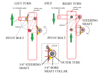
In the drawing below, you are looking straight down, over the top of the frame rail.
The first mechanism is actually bolted to the sides (left & right), but the working parts are situated underneath the bottom of the frame rail.

Redo

I had two different designs. Old on the left, the new design is on the right.
I wanted to clean up the pivot point that was to be on the left outside of the frame.
So I slide everything over to the right and centered the pivot points in the middle of the frame.
One attached and the other free moving.
I will have to measure travel distance, so as to determine each arm/lever length.

Looking at the weld bolts, I just remembered I have some grade 8 shoulder bolts that just might work for this.
Steering Design-4.png
 
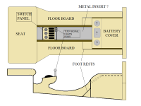
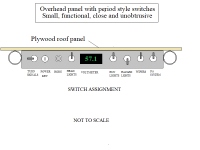
Just another thought about using the switch panel or similar.


This overhead location is much easier to get to and it isn't quite as visible.
But I'm still not satisfied.


Some body and windshield frame mod.
Because I needed to raise the roof,(no pun intended), a couple of inches, I had to modify the top portion of the windshield.
So another lawn chair is sacrificed because it has nice factory corners.


The urge to get started on the steering, hit today.

I'm using a support tube from a salvaged basketball hoop framing.
Wedged in is a 3/4" bore shaft collar. One on each end. The top shaft collar is welded near the top of the post.
The bottom is plug welded in. I took advantage of a hole that was already there.


The top of the column/post is 18 " from the frame top to the bottom of the steering wheel.


Next is to cut the 3/4" shaft and weld on a hub for securing the steering wheel.


My knees come just about the same height as the top of the steering wheel.


This is what I'm working off. It isn't exactly what the finished steering will be like, but it's close.
I haven't decided if I want/need to go to, the bother of making the DIY tilt-away option.
Looked online for quick release adapters, one which would work just right.
https://www.speedwaymotors.com/Speedway-Hex-Quick-Release-Assembly-3-4-Inch-Steel,112635.html?sku=91032847-BLU&utm_medium=CSEGoogle&utm_source=CSE&utm_campaign=CSEGOOGLE&gclid=EAIaIQobChMI2amEl4Ct6AIVENlkCh0sRQPiEAkYCyABEgJ9SfD_BwE
While setting it up, I was in/out and up/down frequently and did quite fine.
I'm sure when it's secured it won't fall over as many times... :D
Though it could be a detail used for conversation.
Also, the front brace won't be quite so large.


It's just visible, but near the bottom, just above the magnet is a bolt, that will be used to secure a front brace.

 
Ok, the column is done and bolted to the frame.

DSCN4417.jpg

DSCN4423.jpg


Doing a fit check. Can't decide if I should keep the tall shaft, and maybe use it as a flag pole, or cut it down to size.

DSCN4418.jpg

DSCN4421.jpg
 
here's a recording of some jet engines spooling up, that should mess with some people's minds. ;)

https://www.youtube.com/watch?v=kmo_lc4uHeQ
 
fechter said:
What happened to the Alien lights?

Maybe next time...
They're still around fechter. I just have them in stealth mode at the moment.

amberwolf said:
here's a recording of some jet engines spooling up, that should mess with some people's minds. ;)

https://www.youtube.com/watch?v=kmo_lc4uHeQ

This is another great idea. :bigthumb: I have put this in my hold folder until I get to that point.
I will throw the best sound into my movie maker app and combine the sounds.
Imagine sitting on the tarmac, waiting for the parade to start, and we get clearance to roll.
I flip the switch and the engine starts, with the jet sound, and then transitions into the roar of a mighty V8.
How cool is that.....so much fun coming :D
Man, I wish this thing was done so I could start playing with it.
 
Steering Update

Cut out the hub and got it welded in place including the center cap post, twice!


The hub is solid mount at the moment but is ready for modifying to full tilt, later.


The center cap is salvaged from an old lighting fixture.


Using my C.A.M (Cardboard Aided Mockup), I've narrowed down the lengths for the steering levers.
Steering post link @ 4"
Connecting link @ 8"
'Pitman' arm length @ 5"

It seems to work just fine, but will have to see what the 'hardcopy' does.


Enjoy
 
Steering Trial Run

As this is the first time checking it for ease of operation, there are some adjustments to be made.
But if it works on the road, it will be great.
I'm still looking to install a steering column/box with gearing later on.

https://www.youtube.com/watch?v=agSpFG420nI
https://www.youtube.com/watch?v=XRQiSGj4I8Y
 
Steering Update

Although I have the steering in working order, I am not satisfied with the outcome.
I've been searching and searching for more appropriate options. They are either too large physically or too large money wise.

Been looking at the various types as well, such as boat steering mechanisms.
Still not satisfied. I may go back and visit with my golf cartman and re-look at what he has.

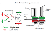
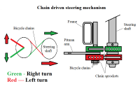
In the meantime, I have drawn up another DIY option.
The drawing shows the sprockets directly next to each other but would, in fact, be staggered.
Thus using the current position of the column and pitman arm levers....get it?

Using sprockets from some old cassettes I have, I can make up the mechanism you see in the drawing.
Playing around with the different sizes will get me a comfortable gear ratio as well.
At least that is the theory. I'm thinking somewhere around 5:1.
Chain drive steering.png
 
if it helps, there's a fair bit of info about chain drive steering out there. so much so that the following search may have more than is helpful.
https://www.google.com/search?q=Chain+drive+steering

the biggest problem is that it is difficult ot get all the slop out of a chain drive, and *any* slop in it will cause lots more slop at the wheels themselves--they may actually wiggle back and forth as you go down the road, and make it hard to control. :(

another issue is that chain with less slop in it is usually stiffer against sideways bending, too, so the sprockets at each end must line up perfectly, and any tensioners in the path must also line up perfectly, or the chain can be pulled up onto the teeth and damage either chain or sprockets or both, *and* stretch things at the same time to add slop to the system. :(


if you can do cable steering instead, and have enough length between the steering column and the tie-rod-actuator system at the wheels, you can use turnbuckles in the cable between them to ensure tension is always correct (as the cable stretches, it's easy to retension). just use thick enough and strong enough cable for the load.


another option is a tie-rod between a lever on the end of the steering column and a lever on the pivot of the steering mechanism, and a bearing on each end (heim joints, etc). this is what i used for crazybike2's remote steering--just a piece of threaded rod with heim joints on either end, bolts that fit perfectly in the joint holes to then secure the rod to the handlebar steerer, and the fork steerer. different length levers at each end gives a non-1:1 steering ratio.
 
I guess it would help to see what the linkage looks like on the front wheels.

Is there some reason the Pitman arm can't be attached directly to the steering column? The arm would need to come out on the inside of the frame and the linkage would be a little diagonal to the attachment point on the front hub.
 
Amberwolf - Thanks for that info. It has made me pause a bit, to see how I want to proceed. To do this 'right', I'm thinking for this part of the build anyway, I'm really smarter by buying the correct component for the task...though that will mean $$$.

Currently looking at a couple of options.
https://www.ebay.com/itm/174050627588?ul_noapp=true

Or this:
https://www.ebay.com/itm/264510850709?&ul_noapp=true&autorefresh=true

fechter - With the pitman arm coming off the steering shaft and connecting to the drag link the direction of the wheels is opposite...steer right go left...steer left go right.
So there needs a mechanism to change the direction...either a steering box or linkage similar to what I fabricated.

Chain drive steering.png
 
I've bitten the bullet and put in an offer for this

https://www.ebay.com/itm/Cub-Cadet-70-100-Up-Ross-Steering-Column/264510850709?hash=item3d96134695:g:rwoAAOSwAGhdsxTC

If it is accepted, I will have to cut the shaft down from 25-26 inches to 19 inches.
Or maybe change steering wheel style.

If I leave it at the taller length there would be more legroom, but it may look out of place.

We'll have to wait and see if the offer is accepted.
 
Thanks, amberwolf, I hope you are happy with yourself.
You've cost me $193.95. :lol: Why am I laughing ?????
But it's for the better.

Well, it's done..he accepted my offer of $180 including shipping. Didn't think about tax until too late. So it cost me $193.95. Didn't really want to put that much money into it, but the quality of the project will benefit.

AND, I got the last one. For real! The original posting now say's 'ended'

It is supposed to arrive by April 3.

https://vod.ebay.com/vod/FetchOrderDetails?sspagename=STRK%3AMESO%3AVPS&itemid=264510850709&transid=2566526917016
 
amberwolf said:
um...ok. i have no idea what that is or does, though. doesnt' look anything like any of the things i was talking about. :?

This should explain it.
Only the first few minutes explain what it is and how it works.
https://www.youtube.com/watch?v=J67L5D1oq5Q
I may have paid more than I needed, but this one is supposedly refurbished. So I thought, why not. It saved me buying all the parts, and doing it myself. All I need to do now is figure how to mount it.

I've got to order some more Heim rod ends. Also another length of larger tube for the drag link. My original one got bent somehow. It will work but I want to make a larger one anyway.
 
I've enjoyed reading this thread during my new found (lockdown) spare time. Well done Ed on producing such a fun and unique vehicle. You've shown admirable persistence in coming to terms with the electrical side of the project and it is clear your knowledge is expanding rapidly from the early posts and their basic misunderstandings to now producing relatively complex and appropriate wiring diagrams. My hat's off to you sir.

Also thanks Fechter and Amber Wolf as always for your knowledgeable and educational input.

Stay safe all.
Giles.
 
The Apprentice said:
I've enjoyed reading this thread during my new found (lockdown) spare time. Well done Ed on producing such a fun and unique vehicle. You've shown admirable persistence in coming to terms with the electrical side of the project and it is clear your knowledge is expanding rapidly from the early posts and their basic misunderstandings to now producing relatively complex and appropriate wiring diagrams. My hat's off to you sir.

Also thanks Fechter and Amber Wolf as always for your knowledgeable and educational input.

Stay safe all.
Giles.

Thanks Apprentice.

Your comments are welcomed. I came here seeking help and I found that and more. Fechter and Amberwolf have been doing this for a veerry long time, yet they still offer great opinions and super advice. They deserve all the credit.

And for persistence, I think the award goes to those two gentlemen. Especially when the student doesn't pick up on the subject quickly. Having been in a teaching position for a few years I know how important that quality is.
 
Back
Top