Just_Ed
10 kW
SlowCo said:Great result :thumb:
Wiring and then powering it up always is a little nerve-racking.
Does having the fire dept
SlowCo said:Great result :thumb:
Wiring and then powering it up always is a little nerve-racking.

.JPG")

fechter said:I like just the drink holders. You may need them removable or have a hole drilled in the bottom to deal with spills.


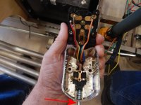
Seems like the emergency flasher thing is stuck on.
Otherwise, you're doing what I would try to do. Trace out the wires and see where the current flows.


amberwolf said:I may be misunderstanding, but if the problem stops when the pilot light is disconnected, then it sounds like the pilot light may be connected directly across the system ground and the flasher input, so it just always makes the flasher operate, and always blinks the pilot light. (it should be in series with the flasher input, so it only operates when one or more signals are operating in flasher mode).
But that wouldnt' explain the overcurrent / shorting problem(s). That sounds like a miswire internally, where one of the color coded wires isn't wired to the terminal it is supposed to be, from the factory. So when you follow the provided wiring diagram, it ends up shorting something instead.
I'll have to ponder the physical connections visible in the pictures vs the wiring and see if I can figure it out.
 :x
:x
fechter said:If I can find time, I'll try to trace out your circuit. Your exploded pictures should be enough to figure the thing out, but it is complicated. Clearly, the supplied wiring diagram is not quite correct. Possibly some colors got switched around. It's hard to visualize how the contacts are aligned in all positions. I'm sure there's a way to make it work.
j bjork said:I hang up on in the wiring diagram there is no ground, the black wire goes to the relay.
But in your picture the black goes to ground?