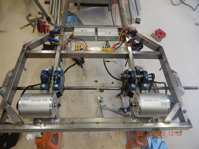
C Cab Hot Rod Power Advice

Hillhater said:
Ok, but using those dims,. You could get a 9” dia brake rotor on with an extended JS
But no big deal if you are committed to the existing set up.
..( but its good to know my eyeball is still calibrated ! :wink: ) :thumb:

Not really sure that I 'need' such a large rotor.
Remember I'm only doing a max of 25 mph.
Maybe two of these would do just as well.
https://www.ebay.com/i/303250940548?rt=nc&_trkparms=aid%3D1110001%26algo%3DSPLICE.SIM%26ao%3D2%26asc%3D225074%26meid%3D1486e365e13547169e0721307bc9aaf2%26pid%3D100677%26rk%3D12%26rkt%3D30%26mehot%3Dnone%26sd%3D283684236525%26itm%3D303250940548%26pmt%3D1%26noa%3D1%26pg%3D2386202
 
The idea of large rotors is not just stopping power but more about getting rid of heat. If you do not have regen and use the brakes a lot in a heavy EV you will make a lot of heat and ware out and/or warp the disc/rotor. My regen is more about stopping the watts recovered is a bonus. so I have never upgraded my front breaks if I did not have regen I would go to larger discs.
 
ZeroEm said:
The idea of large rotors is not just stopping power but more about getting rid of heat. If you do not have regen and use the brakes a lot in a heavy EV you will make a lot of heat and ware out and/or warp the disc/rotor. My regen is more about stopping the watts recovered is a bonus. so I have never upgraded my front breaks if I did not have regen I would go to larger discs.

Ok. Thanks for that bit of insight.
I compare their use to that of a go kart, which is braking hard and often, at high speeds.
I suppose if they can use the size I'm looking at, they should work on my creation.
 
I think the go kart discs should be pretty good. They look on par with what you would find on a motorcycle. Typical bicycle brakes are much thinner and lighter.
 
fechter said:
I think the go kart discs should be pretty good. They look on par with what you would find on a motorcycle. Typical bicycle brakes are much thinner and lighter.

Yeah, I have a set of new disc's & calipers, (cable) for bicycle, but I wouldn't want to trust them on this project.
 
Slow But Sure @ 1/4 steam ahead

While I'm looking into converting (later) to belt drive, and what I learn in the meantime,
progress on the chain drive system moves forward.

The body has been restricting my movements and ability to see well enough to weld.
So this morning, off it came. (A design element :D)

DSCN4326.jpg


MUCH easier. I was able to see much better, and getting into and out of position to work,
will greatly ease those parts, that aren't wanting to cooperate anymore.

Got the motor mounts welded in and bolt holes drilled.
Bottom needs welding, but that will come later.

DSCN4328.jpg


After some modification of the 'bicycle chain breaker', I am able to break the chain apart.
Still I must find one suitable for this heavier T8F chain.

DSCN4329.jpg


So it's tighten up, then tidy up, and move on to the second jack shaft installation.

Then maybe I will look into wiring it up, for a function test.

Ran out of (or can't find) any more 3/8" bolts or threaded rod to make more.
Chains are made to length, and installed, and are near perfect for tension, as they sit.

DSCN4330.jpg

DSCN4331.jpg


Oh! did you notice the change?
 
Do you know if your controller has regenerative braking? Just curious. For flat ground it's not worth it in most cases but great on hills.

The chains will tend to 'stretch' over time and you might want some way to adjust the slack. If not using regen, then you could add a spring loaded tensioner roller between the sprockets. Those chains are pretty short though, so maybe won't be a big deal.
 
fechter said:
Do you know if your controller has regenerative braking? Just curious. For flat ground it's not worth it in most cases but great on hills.

The chains will tend to 'stretch' over time and you might want some way to adjust the slack. If not using regen, then you could add a spring loaded tensioner roller between the sprockets. Those chains are pretty short though, so maybe won't be a big deal.

Regenerative Braking

If you mean stop the aging process and give me a full charge.....I'M TOTALLY IN :D

But if you mean the mundane type, then I don't believe there is regen, with the controller I have.
I'm not knowledgeable at this point, to really give any opinion.
What I think is close to accurate, is the controller I have, does not have a 'regen' connector,
for a brake handle or momentary switch, with which to activate the regen.

Chain Tension Adjustments

There are elongated slots, in the pillow blocks, forward/backward, for the motor to JS chain.
The PB holes are centered as you see in the photo. The chain is taut at this point.

For the JS to axle, I will use shims, under the pillow blocks to lift/tighten, the vertical chain.
An equal amount/thickness for both pillow blocks, thus keeping the JS axle running straight.
 
My pillow block bearings were supposed to arrive tomorrow, but arrived today.
But while I (was) waiting for them, I made a couple of corner braces, for the rear of the frame.

DSCN4334.jpg


With my motor and gears/chain, securely protected, I proceeded to weld the braces in.

DSCN4335.jpg


I had no sooner finished making the supports for the new pillow blocks, when I took a short break and discovered they had arrived.
So tomorrow, the plan is to make two motor mounts, have some coffee, drill some holes, have some coffee, make JS axle, have some coffee, have a nap, have some coffee, shorten a couple of chains, have some coffee. And while I'm having coffee, I will think about what to do before .. I have my next coffee.

DSCN4337.jpg


In case anyone missed ...'the change'...I reversed the motor orientation.
 
Didn't get 'everything' done yesterday.

Didn't get the chains made, and I didn't get my nap!

This morning before going out, and while my brain cells are in the mood, I worked on the wiring. (power only)

I needed to take the schematic that was supplied, and make it work with my two motor, two controller setup.
The idea here, is to gain understanding of how and where things will/may go, and what gets connected to what,
with out setting my shop on fire, or toasting any components.


Below is the schematic supplied with my motors.
I'm not including any accessory wiring in this exercise.

 
One thing that will be important is to have a very low resistance connection between the two controller B- connections. Use heavy wire and keep it as short as practical. This is because you are going to share the throttle between the two and any voltage difference can affect the throttle signal. Your drawing looks OK.

When you get to the accessories, you might want to consider a 12v dc-dc converter to supply 12v for lights, etc. There are many to choose from depending on how much load you want. Here is an example:
https://www.ebay.com/itm/1pc-DC-DC-...e=STRK:MEBIDX:IT&_trksid=p2060353.m2749.l2649

Another handy thing would be some way to measure the current draw when running and a battery "fuel gauge". Again there are many possible choices. The Cycle Analyst is popular here, but pretty expensive. Here's a link:
https://www.ebikes.ca/shop/electric-bicycle-parts/cycle-analysts.html

A less expensive alternative is a TK15 or similar. I have a couple of these and they work OK but the screen is pretty small.
https://www.ebay.com/itm/50A-100A-3...hash=item2ce0b12abb:m:m81rVlXUzxMlPpYo5IqS5xw
 
fechter said:
One thing that will be important is to have a very low resistance connection between the two controller B- connections. Use heavy wire and keep it as short as practical. This is because you are going to share the throttle between the two and any voltage difference can affect the throttle signal. Your drawing looks OK.

When you get to the accessories, you might want to consider a 12v dc-dc converter to supply 12v for lights, etc. There are many to choose from depending on how much load you want. Here is an example:
https://www.ebay.com/itm/1pc-DC-DC-...e=STRK:MEBIDX:IT&_trksid=p2060353.m2749.l2649

Another handy thing would be some way to measure the current draw when running and a battery "fuel gauge". Again there are many possible choices. The Cycle Analyst is popular here, but pretty expensive. Here's a link:
https://www.ebikes.ca/shop/electric-bicycle-parts/cycle-analysts.html

A less expensive alternative is a TK15 or similar. I have a couple of these and they work OK but the screen is pretty small.
https://www.ebay.com/itm/50A-100A-3...hash=item2ce0b12abb:m:m81rVlXUzxMlPpYo5IqS5xw

One thing that will be important is to have a very low resistance connection between the two controller B- connections.

I'm not sure what you are referring to here...between the two ( controller B-) connections.

This mornings work

Installed the two cross pieces, and found a great place for the controllers, and terminal blocks.
I'll enclose the bottom, and have a vented top.


This all I have to monitor with at the moment
 
Turned cooler, wind chill factor, threat of rain, and windy. Time to work inside.

Trying to make sense of all the wires and connectors.
They're not all marked, so there is a bit of a hunt and peck trying to find what goes with what.
The controllers are marked, so that helps. But not all color coding is the same.
I may have to unwrap the wire harness, as it isn't really setup for my application.


I've marked my motors, so I won't loose track, of which is which....:D


Preliminary setup. Still need to figure out how the wiring harness is going to work into this.
With what I have connected so far, (please correct me if I'm incorrect) in my wiring.
I think that all that is needed for just a motor function test,
is to energize the two battery cables, and see if the sparks fly. 😬
Or maybe just stick'em on there.
I'd be using the battery circuit breaker for a switch.

And yes I know the battery cables do not have ring terminals...YET !

 
fwiw, i'd mark the motors and controllers (and any other dual parts) as "left" and "right", so they can all be easily kept track of without a reference chart for which is which. ;)


for the battery wiring, i would use the heaviest gauge you have available; it helps prevent voltage drop between battery and controllers, *and* from differences in current flow between controllers causing ground to rise on one vs the other, relative to battery ground, and throttle ground / etc. I think i'm using 8g on my sb cruiser trike, might be 10g though.


there is good info on 2wd wiring systems over in teklektik's yuba mundo cargo bike thread.
 
fechter said:
One thing that will be important is to have a very low resistance connection between the two controller B- connections. Use heavy wire and keep it as short as practical. This is because you are going to share the throttle between the two and any voltage difference can affect the throttle signal. Your drawing looks OK.

When you get to the accessories, you might want to consider a 12v dc-dc converter to supply 12v for lights, etc. There are many to choose from depending on how much load you want. Here is an example:
https://www.ebay.com/itm/1pc-DC-DC-...e=STRK:MEBIDX:IT&_trksid=p2060353.m2749.l2649

I need some clarification what is meant by; between the two controller B- connections.
What are, ( B- connections) ?
Are you by any chance referring to the jumper wire from one terminal block to the other?

I suppose there is no time like the present, to get the converter. If I had it now,
I could size it to the same location, (or not), that I am placing the controllers.

Buying a converter is not a problem, I just need some understanding, why?
I thought the controller did the same thing?
If not, why are all those wires coming out of it? :)
 
Just_Ed said:
I need some clarification what is meant by; between the two controller B- connections.
What are, ( B- connections) ?
Are you by any chance referring to the jumper wire from one terminal block to the other?

that, and the connection to the negative of the battery. (battery negative = b-, battery postive = b+)

i'd do the positive wires in the same gauge, just because. ;)


Buying a converter is not a problem, I just need some understanding, why?
I thought the controller did the same thing?
If not, why are all those wires coming out of it? :)
hte controller converts battery power into motor power.

if you need power for lights and stuff, that's a separate thing, and either uses a separate battery (like i do on my sb cruiser trike), or a dc-dc to convert the higher traction battery voltage down to the 13.6-14.4v that automotive lighting and accessories use. (you don't want just plain 12.0v, as it will mean dimmer lights, etc., so make sure you get one that's at least 13.6v. some automotive-level dc-dcs are marked as 12v covnerters, but have a voltage spec that's the higher voltage range, and that's what you're after. (or one that's adjustable up to that). i recommend the ones taht are potted and sealed, because while that makes them essentially unrepariable, it also makes them less likely to need repair from environmental conditions.
 
I'm definitely going to be needing the lights, horn, sound system, heater, A/C, power seats, well maybe not those last three.
Spent time looking for converters, that indicate a higher than 12v output. Couldn't find any, or specs that indicated such.
So it's hard to tell what one is buying.

Also, I'm not wanting to wait a month or two for parts to come from China, even if it means paying a bit more.

I did find this one....what's the opinion of this?

https://www.amazon.com/Pro-Chaser-Converter-Complementary-Connectors/dp/B07S6G4Q66/ref=pd_sbs_23_2/132-6121787-4384133?_encoding=UTF8&pd_rd_i=B07S6G4Q66&pd_rd_r=a81c088b-367a-4b23-81ce-76bdd581558a&pd_rd_w=ItRcH&pd_rd_wg=ddKUO&pf_rd_p=7cd8f929-4345-4bf2-a554-7d7588b3dd5f&pf_rd_r=AWCNE04DCGKFZ09M4PD5&psc=1&refRID=AWCNE04DCGKFZ09M4PD5
 
It would be best if the main negative wires were connected directly to each other on the terminal block. This also goes to the battery. If the negative battery connection between the two controllers gets loose or has too much resistance many bad things can happen.

I would flip the controllers around so the wire ends face each other but either way can work fine.
 
fechter said:
It would be best if the main negative wires were connected directly to each other on the terminal block. This also goes to the battery. If the negative battery connection between the two controllers gets loose or has too much resistance many bad things can happen.

I would flip the controllers around so the wire ends face each other but either way can work fine.

Hows this? Don't look at the connections, this is just to see what's what.


Trying to place 3 rings on one terminal is iffy, at the moment. The studs are very short. Barely over the depth of the nut.
I think the 'rings' would fit, but the crimped portion makes it. 'iffy'.

I checked the wire size from the controller, and they measure 12 gauge, (with solder on it), so maybe it's only 14.

Looking at it in the picture, makes me think maybe. When I go back out, I will give it a try, with the two smaller wires, (12 AWG & 14 AWG) on one side, and the 8 AWG on the other.
 
Just_Ed said:
Spent time looking for converters, that indicate a higher than 12v output. Couldn't find any, or specs that indicated such.

a google search for "48v to 13.6v dc-dc"
https://www.google.com/search?newwindow=1&q=48v+to+13.6v+dc-dc
finds a few pages, like this one
https://www.powerstream.com/dcdc-48V.htm
that have a few 13.x v supplies, but they're really really expensive. a few other links i randomly checked also have some, but they're still expensive, as most of them are in the 50-100a output range.

you can always still use the 12v versions, and they'll work just the lights will be a bit dimmer / etc.

it's also possible that some fo the 12v units will be 13.x v output actaul voltage, but unless they're spec'd as that, you won't really know till you test it.
 
Just_Ed said:
Trying to place 3 rings on one terminal is iffy, at the moment. The studs are very short. Barely over the depth of the nut.
I think the 'rings' would fit, but the crimped portion makes it. 'iffy'.
you could take one of the short studs out, and replace it with a longer bolt. (making sure to insulate between it and the frame).
 
amberwolf said:
Just_Ed said:
Trying to place 3 rings on one terminal is iffy, at the moment. The studs are very short. Barely over the depth of the nut.
I think the 'rings' would fit, but the crimped portion makes it. 'iffy'.
you could take one of the short studs out, and replace it with a longer bolt. (making sure to insulate between it and the frame).

I'm not sure, but I think those studs are molded in. So there is a possibility there may be breakage. The block feels like pot metal. It's not plastic. Maybe aluminum. I'll check it with a magnet tomorrow.
At $16.00 bucks a pop, I'd sooner not break one.

However I did try to place three rings on and it didn't work. The ring end I have for the 8 AWG wire is thick,
so it takes up the space of at least two of the others.

I can make a stud, connector/extender, using 2-3 nuts and a longer stud.
Or I can just use two jump wires as I originally had. If so, I would put the battery leads,
separate from the controller leads. And double up on the controller leads. (2 x Black) & (2 x Red). All will fit then.
 
Just_Ed said:
I'm not sure, but I think those studs are molded in. So there is a possibility there may be breakage.
they probably are molded in; you'd likely have to drill it out in a press to prevent breaking the plastic block. it's probably easier to just use two studs right next to each other for each of the batteyr connections, to keep the interconnect between them a very very short U.

The block feels like pot metal. It's not plastic. Maybe aluminum. I'll check it with a magnet tomorrow.
it can't be metal, or it would conduct between the studs. ;)

i don't know which plastic it's made from, but it'll be some high density stuff.
 
Back
Top