Changing the LVC in a 72v generic controller

P.S: I think I found a boo boo in your math. (I may be wrong, though, so do check!)

[EDIT]I just saw that you're using a lithium pack and need different values. I'm basing these on what I need for my SLA bank for a proportionate scalling down of the lvc to 2/3 of what it will be for the controller in its 72V 'mode'[/EDIT]

Formula for "adding" resistors in parallel:
1/r = 1/r1 + 1/r2 + 1/r3

For three 1500Ω resistors we have:
1/r = 1/1500 + 1/1500 + 1/1500
=> 1/r = 1/500
=> r = 500Ω

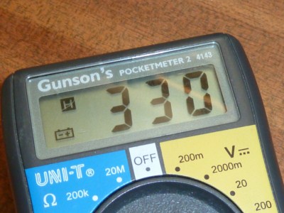
We want to reduce this to the ratio of 48/72 = 2/3 => 333.3Ω
(In other words, we only need two thirds of this resistance value to knock down 48V to what the board wants)

What YOU have is (one REPLACED by a 1K resistor):
1/r = 1/1500 + 1/1500 + 1/1000
=> 1/r = 0.000666.. + 000666.. + 0.001 = 0.00233..
=> r = 428.57 :(

What you WANT is (a 1K resistor ADDED in parallel!)
1/r = 1/1500 + 1/1500 + 1/1500 + 1/1000
=> 1/r = 0.000666.. + 000666.. 000666.. + 0.001 = 0.003
=> r = 333.3Ω :)

In other words, you need to ADD the 1K resistor in parallel, not replace one of the existing ones :)
If I'm right, I'll bet the "slight drop" in voltage you saw was about 14.2%... ?
 
Thanks zenid I'll try that it a bit.
I just tested the setup with the 1k resistor, and it didn't do anything. (I have a throttle now and the motor wired up to the controller)
Just an LED flashing 8 times, which is the code for LVC for wilderness energy kits.

I e-mailed evassemble and asked for more information about these controllers, so maybe they can shine a light.
 
Well, my 36V version already uses 333ohm (331ohm actual), so assuming these are the same basic controller, then that'd be too low for 48V.

Since they may not be identical in other ways, it's hard to tell without a test.
 
amberwolf said:
Well, my 36V version already uses 333ohm (331ohm actual), so assuming these are the same basic controller, then that'd be too low for 48V.

Since they may not be identical in other ways, it's hard to tell without a test.
Yes! I wondered about that, as I would have expected your 36V controller to - by this theory 0 have only 250Ω
But then I realised: While yours is a 12 FET, these are 15FET. I heard elsewhere that this acts as a multiplier in these calculations so:

12/15= 0.75
333.33 x 0.75 = 250 Ω :D

In other words, IF yours had 15 FETs, it would indeed need 250Ω, here as opposed to the 500Ω used by the 72V controller.

But you're quite right, the only way of proving this is by making the mod and testing it, which -time permitting - I'll have a go at today... I just have to get hold of a good size 1KΩ resistor. I'm going for a 7W one, as I'm not convinced that the sm aller one (3W?) used by Talespin would live very long, as it would be drawing more current that the others (less resistance).
 
auraslip said:
Thanks zenid I'll try that it a bit.
I just tested the setup with the 1k resistor, and it didn't do anything. (I have a throttle now and the motor wired up to the controller)
Just an LED flashing 8 times, which is the code for LVC for wilderness energy kits.

I e-mailed evassemble and asked for more information about these controllers, so maybe they can shine a light.
Your resistor change has only lowered your resistance to around 428/500Ω, that translates to lowering the voltage cut-off to about 53.6V (assuming a built-in cut-off of 62.5V).

Which means your 48V battery pack (if it's lithium) is not still not going to reach that point. As I understand it, while SLA packs have a range of ±12-15% or so (56V fully charged, 40V depleted) this is NOT the case with lithium packs. So my first prediction, here, is that your voltage is ineed under this threshold, like Amberwolf said.

So I'll bet the little red light is an lvc cutoff warning light. I'm off to get a 1K resistor, but I think I'm going to put it on the other side of the board, on the plate where all the resistor legs meet - it's less cluttered.

The great thing about this mod (if it worked), is that you would potentially have it 'switchable' in a rudimentary way: Snip the extra 1K resistor, and you 'upgrade' the board to 72V :)
 
On the back, you can see the two plates that make it clear that the resistors are all connected in parallel, and a multimeter reading does indeed give 500Ω.
48vc2-20.jpg


So, here's my own mod, with a 1KΩ 7W resistor in parallel
48vc5-20.jpg


Giving the 333Ω (about) that I want.
48vc3-10.jpg


So I took my bike to pieces, removed two batteries, and rewired back into the 48V configuration. I hooked up the new controller, and powered it up with the hall sensor disconnected at first, to take a reading, It read 4.7V. So far so good...

But then I plugged in the hall sensor, powered it up and tried the throttle and... nothing :( Sliding the PCB from its case in situ reveals the blinky red light of doom :(

Bummer... what are we missing here? I thought this should have fooled it into thinking it was connected up to 72V, but evidently something's missing. Now my suspicion is this: There are two power inputs to the controller - the high current one for the FETS, and a low current one (the thin red wire) that the ignition turns on and which takes care of other stuff (powering the CPU?). I think that maybe modding this resistor only takes care of the high current part, but not the other part of the circuit.

Does anybody here who knows a bit more about controllers have any idea about what else might need changing, and where it would have to happen?

[EDIT] The blinky red light gave the same 8-flash lvc error as auraslip got
 
auraslip said:
We really need a pin out from the mcu.... with that we could back trace the voltage dividers coming off the lvc input. Until then it's just a guessing game!
Could you explain this? My understanding of these boards is limited... Where's the 'lvc input' and 'voltage dividers'? What do they look like? Is the mcu that CPU that is programmable on better boards?

I thought our reasoning here was basically okay - we're fooling the board into making our 48V appear as a 72V would to the motherboard circuitry, with the lvc being scaled down accordingly. Is there somewhere that gives a good explanation of how these things work?
 
Well every board is different.... but basically the resistors we changed were part of the 5v regulator system meant to provide 5v to the hall sensors and other controller parts. The mcu probably has a trace leading towards it that senses a voltage and uses that to determine LVC. Whether this feeds of the 5v regulator system is undecided, but it probably is. We just need to find out which pin to the mcu has the voltage dividers(resistors) attached to it that decides LVC.
 
Well here are some close-ups for anyone who might want to try and help decipher this. The threads to the left of the mcu are attached to various bits and bobs that could be of interest, it's a question of figuring out which one. Also these things are tiny and I think you'd need near-microsurgeon precision to do anything with them...
This one - I think is the most promising:
http://zenid10.files.wordpress.com/2011/03/mcu2-1600x1200.jpg

http://zenid10.files.wordpress.com/2011/03/mcu1-1600x1200.jpg
http://zenid10.files.wordpress.com/2011/03/mcu5-1600x1200.jpg

The markings on the board must be a clue. Any idea what they mean. The RXD is interesting, as it's usually part of a TTL interface.

The threads to the right don't seem to be as many, but interesting is that 4-way junction, which looks like it might be for a TTL interface (though the RXD is elsewhere on its own). Even with a USB/TTL interface, getting software to talk to the chip is a different matter entirely though...
http://zenid10.files.wordpress.com/2011/03/mcu3-1600x1200.jpg
http://zenid10.files.wordpress.com/2011/03/mcu4-1600x1200.jpg
http://zenid10.files.wordpress.com/2011/03/mcu6-1600x1200.jpg
 
http://zenid10.files.wordpress.com/2011/03/mcu2-1600x1200.jpg
I was thinking that bottom trace running from the MCU and then down to the left might be the lvc one. It seems to feed right off the main voltage regulator, and run through some voltage dividers and then directly into the mcu. It was at like 2.5v with my 48v charger. I was guessing that was the one because it doesn't seem to have any other function.... I'd learn how to replace the smd resistors on that trace, but I've run out of time to work on this controller because I got a new bike to build as well as school work!
 
auraslip said:
http://zenid10.files.wordpress.com/2011/03/mcu2-1600x1200.jpg
I was thinking that bottom trace running from the MCU and then down to the left might be the lvc one. It seems to feed right off the main voltage regulator, and run through some voltage dividers and then directly into the mcu. It was at like 2.5v with my 48v charger. I was guessing that was the one because it doesn't seem to have any other function.... I'd learn how to replace the smd resistors on that trace, but I've run out of time to work on this controller because I got a new bike to build as well as school work!
I'm afraid you'll have to bear with me, I'm not strong on the jargon. Where is the 'main voltage regulator'? - Do you mean where those big resistors step down the external voltage to the 5V needed by a lot of the components on board? (I don't even understand how you can get 5V from 72V and 500Ω :? )

Yes I had my eye on that little brown resistor(?) by "M4". I tried to measure it with my multimeter, but the reading fluctuates upwards as soon as I try - I think the meter must be charging up a capacitor somewhere or something...

I have a little time on my hands. If I can have some direction as to how to figure this out (safely!) I'll experiment on my board. The first stage - like you say - is figuring out how to replace those teensy little resistors :shock:

[EDIT] I've figured out how to read those teensy resistors and confirm their value. Are those little brown things capacitors? They seem to behave like that when I measure them...
 
dude I'm only like one step ahead of you lol... a month ago I didn't know what any of this meant!

Maybe we should rename this thread and put it in the ebike tech section, or perhaps we can make a new thread there. It'd likely garner more attention.
 
I'll move it and rename it, just tell me what you want it called. Also, all of us will need to re-subscribe to the thread once moved, as that breaks subscriptions for some reason. ;)
 
Thanks Amberwolf!

So... Can anyone out there help us figure out what might need changing in these generic 72V 'McControllers' in additon to the resistor mod detailed above? A hyperlink to existing, relevant discussion would be nice as even with search it's not always easy to locate relevant, existing discussion... :?
 
On some documentation for the infineon controller, modifying the lvc from the board is detailed as follows:

"The Low Voltage Cut-off (LVC) circuit consists of tiny surface mount transistors and one capacitor.
This circuit connects to an MCU pin-out so the MCU can detect the battery voltage.
The R12 resistor is about 1.2 kohm and connects from the MCU pin-out to ground"

infineon-r12.jpg


Some info from a website on how controllers work ("4QD-TEC") also says this about one of their own circuits:

"There is also an on-board regulator: power input is to pin 15 (pin 8 is 0v), pin 16 is a regulated reference voltage output of 5v. This is used to drive the speed control pot (the 3 pin connector). It is also used to drive under-voltage shutdown into pin 10"
"If you discharge a lead-acid battery too much you permanently shorten its life. So this circuit measures the supply and compares it with the 5v reference supply. If the battery voltage falls too low the transistor inhibits the pwm circuit by feeding a signal to pin 10."


So what we need is to identify the corresponding resistor on the "X6M06" board, that might correspond to Infineon's R12:
Looking at the tracks from the mcu, you can see that many of these don't seem to serve any purpose and simply terminate nearby, so they can be ruled out.
mcu1-640x480.jpg


Panning back a bit, you can see how the tracks to the left and bottom of the mcu are organised.
mcu2-640x480.jpg


The infineon documentation mentions surface mounted transistors being involved. You can see some of these below right of the mcu (panned right from the previous photo)
mcu3-640x480.jpg


So where would we begin when it comes to testing voltages or continuity to try and identify the correct pin and resistor for the lvc?
 
I'd forgotten about the R12 thing on the XieChang ("Infineon") controllers! That also deals with the regen voltage, IIRC.

If R12 goes from MCU to ground, then presumably R11 goes from MCU to either B+ or the output of those big power resistors.

Whichever way the XCs do it, the XMs probably do, too. Somewhere I have a scrap XC board of the type for that R12 info (other than my working Lyen 6FET on DGA), but cant' find it at the moment.

The other ones I have are older and don't have the same layout/etc. However, the one I checked (the blown one from Auraslip) has an R10/R11 voltage divider that goes from the output of one of the big power resistors to ground, with it's center tap heading off toward the MCU area. I can't get an in-focus pic of it zoomed in enough to see anything, though. :(


I took a gander at the 12FET XM I have here, and it has a few things that could be the voltage divider, the most suspiciously set up of which is the string of four 2.2Kohm resistors here:
Copy of DSC04066.JPG
Copy of DSC04067.JPG
But those resistors are the same value in Auraslip's 72V controller, which nixes that idea, if it is indeed comparable in function/design to the XCs:
VAmxC.jpg

Buuut: I think a comparison of the resistor values between our controllers ought to tell us which ones are good candidates. If we know which ones are different, we can then trace out just those and see where they go. :)
 
amberwolf said:
{...} Somewhere I have a scrap XC board of the type for that R12 info (other than my working Lyen 6FET on DGA), but cant' find it at the moment.

The other ones I have are older and don't have the same layout/etc. However, the one I checked (the blown one from Auraslip) has an R10/R11 voltage divider that goes from the output of one of the big power resistors to ground, with it's center tap heading off toward the MCU area. I can't get an in-focus pic of it zoomed in enough to see anything, though. :(
As luck would have a non-working EB-212 infineon type "XC" board that I got off ebay in the hope of fixing it :) (dew got onto the board when it got left with the case not-quite-closed and it blew a FET, just to add to its non-workingness)...
dc1-640x480.jpg


But I also have an excellent camera with macro zoom and can take snaps of any parts you want, or try and trace various parts if you can give me pointers... :)

[EDIT]
The resistors on my XM seem slightly different to those on Auraslip's... hmmm
p1020016-640x480.jpg

p1020015-640x480.jpg
 
Zenid said:
But I also have an excellent camera with macro zoom and can take snaps of any parts you want, or try and trace various parts if you can give me pointers... :)
I'd just trace the path for the R12/R11 divider, to see where it goes on the XC type. Probably the same as what it appears to be on the old type I checked, above, which uses R10/R11 for that.

[EDIT]The resistors on my XM seem slightly different to those on Auraslip's... hmmm
I can't read the third one from the left, but all the others in the row are 222, which is 2.2Kohm. The bottom one that lines up with the obscured third one is 472, or 4.7Kohm. That's all the same values as mine and Auraslip's, so I think those 5 can all be eliminated as part of the solution to the LVC problem.
 
The problem is I can't find R11 or R12 labels actually BY resistors. At the bottom of this picture along to the right of the big resistor on the 'Infineon' XM board, just under the smaller of two capacitors, you can see "R10, R11, R12" printed all squished together but apparently referring to nothing, unless this is some way of referring to those further up the board.. :?
http://zenid10.files.wordpress.com/2011/03/p1020029-middle.jpg

Here's further up right, towards the tracks entering the MCU
http://zenid10.files.wordpress.com/2011/03/p1020030-top-right.jpg

Here's further to the left... What is that big coppery thing? :?
http://zenid10.files.wordpress.com/2011/03/p1020031-left.jpg

Oh and here's way over to the right so you can see all the mcu tracks as they go off elsewhere.
http://zenid10.files.wordpress.com/2011/03/p1020034-right.jpg
 
Yeah, they do that because there's no room for readable print there. :) Fairly common on SMT stuff (when they bother to label at all).

In "p1020029-middle.jpg", the C5 marking above the column is the top capacitor in that column, and C9 in the relocated printing is the one below it. Then the R-markings are for each of the resistors in that column, in the same order as the markings.

So in that pic, R12 appears to be 122, or 1.2Kohm. R11 would then be either 458 or 856, I can't quite tell. Neither one makes sense to me, given that 458 would be 4.5Billion ohms (I think) and evne 856 would be 8.5Megohms. :? Hopefully I just cant' read the value in that pic. ;) I guess it might also be 85b, but I'm not aware of what the lowercase letter would indicate.

I can't see R10 in the pic, it's obscured by the cap. In the other pic, it looks like it's 01c, which again I'm unaware of the marking standard.


The same goes for the relocated R and C position markings in the other pics.

In the p1020031-left.jpg pic, that large coiled-wire-on-black-doughnut is an inductor (specifically, a toroid inductor). Sometimes simple transformers are made that way, too, but this one only has (AFAICS) two board connections, rather than 4 or more, so it's just an inductor. Probably there to help fight inrush currents into some part of the circuit.
 
Yes, the two bottom ones are 856 and 01C (hidden behind the capacitor in "middle"). The problem is, none of these have a track running to the MCU, which is where this LVC cut-off pin should be hiding, so now I'm just as confused...

However looking back at the "middle" picture, and right by where the main 72V low current feed hits the big drop-resistor, there's the promising "Vcc-L" -(Voltage circuit cutout - low??) But what is it talking about? Could it be where there's an option to solder an extra wire to tell the controller to cut off given a certain signal? It probably isn't even relevant :(
[EDIT fixed link]
http://zenid10.files.wordpress.com/2011/03/p1020029-middle.jpg

Does this give you any better idea of what pin might be accepting the lvc signal from what resistor? It doesn't look to me like resistor 11 or 12 has anything to do with the lvc, otherwise there'd a track going straight into it, right? And if this doesn't give an example of what one looks like, then it's not much good for deciphering our actual XM boards :(

[EDIT]
This looks interesting. This is an old pic from where I prised the capacitor all the way up so the mcu and tracks were clearly visible. There are some candidates coming off the tracks on the right...
http://zenid10.files.wordpress.com/2011/03/p1000533-1600x1200.jpg
 
Zenid said:
Yes, the two bottom ones are 856 and 01C (hidden behind the capacitor in "middle"). The problem is, none of these have a track running to the MCU, which is where this LVC cut-off pin should be hiding, so now I'm just as confused...
It might run from there to some other part that buffers the signal first, and hten to the MCU. A transistor, op-amp, etc.

I still have to find out what the 856 and 01C mean, as they don't make sense as resistor values but I can see that's what they are.

However looking back at the "middle" picture, and right by where the main 72V low current feed hits the big drop-resistor, there's the promising "Vcc-L" -(Voltage circuit cutout - low??)
Vcc is usually used to mean some voltage source intended to power things. Vcc-L likely just means it's a Logic voltage source (as opposed to the FET power/etc), or Low voltage source, to power all the 12V-or-less stuff.

But what is it talking about? Could it be where there's an option to solder an extra wire to tell the controller to cut off given a certain signal? It probably isn't even relevant :(
http://zenid10.files.wordpress.com/2011 ... middle.jpg
The link to your file is broken in the post; it's missing part of the URL, so I can't see what you mean.


And if this doesn't give an example of what one looks like, then it's not much good for deciphering our actual XM boards :(
That's true enough. :lol: :(
 
Back
Top