Commuter Booster - <1kg Friction Drive

Well I just turned it over for the first time on the bike. :D

I even got my 4 year old helping out when he asked why his bike doesn't have a motor on it. :lol:

Good news: IT LIVES ! Wheel turned, nothing blew up.
Bad news: Still needs geometry tweaking to work.

Now I know what you mean by "all or nothing" Todd.

EVTodd said:
From everything I've seen it seems like a sliding system has smoother action as it tightens against the tire. It has none of the all or nothing movement some pivot systems have.

I adjusted things so there was a slight gap to the tyre. Twist the throttle and the motor engages but "bounces" off. This was with the bike hanging in the air, but even trying to apply some braking didn't do the trick.

Probably has a lot to do with the geometry as pointed out by Kepler.

Kepler said:
I am concerned that you will have trouble getting the motor to pick up on the tire with that geometry. With the drive that low on the tire, I think the climb angle is too high.

I did adjust things to improve the angle, but ran out of real-estate. I will have to move the pivot point lower, and/or decrease the pivot arm radius.

Lucky it is quick to do with MDF and a hand drill.

I really need to get myself a mill.

- Adrian
 
adrian_sm said:
umejopa said:
Nice thinking!
I have build a wery simalary system .
First up. Welcome to ES, and thank you for sharing your bike on my little thread. Next ....

Wow. Nice thinking indeed. Awesome work. Very very similar.

Now I have so many questions.

umejopa said:
One thing I hade to do was put the arms togheter so the not twist else the bearing will fall in the motor .
http://www.hobbycity.com/hobbycity/store/uh_viewItem.asp?idProduct=4913

Yep. I plan on the same but was going to use the main pivot axel to tie the two arms together.
But I like your c channel solution. Much simpler, and gives an easier solution to some of the other design goals like limit stops and how to adjusting of them.

Q1: Does you motor totally disengage from the tyre, or is it nominally just touching when not in use? How well does it pick up the tyre?
Well it is about 1-2 mm from tyre and it my swing on to it some time wene only have the gravity yo hold it down in lower possision.
I climb wery well on tyre have to make a better stop this on get longer all the time and it over climb and get looked and then i have put it free.

Q2: What controls how far the motor can move away from the tyre?
The rubber stop

umejopa said:
Running it at 6S 4500mA
http://www.hobbycity.com/hobbycity/store/uh_viewItem.asp?idProduct=11933
and it peak out at 2000W at my watt meter , dont now how accurat that is
http://www.hobbycity.com/hobbycity/store/uh_viewItem.asp?idProduct=10080
Only running a 60A controller but it have not broke yet and I get about 105A peak , They say it will be bulletproof time will tell.
http://www.hobbycity.com/hobbycity/store/uh_viewItem.asp?idProduct=2166
Will get a bigger motor this get to stressed.

Q3: What sort of performance are you getting?
- max speed on the flat / going about 40 kph on flat and about 30 up hill
- wh/km Have not messure that only wene hard on trottel the batteri get emty fast
- what sort of hills can you get up / Dont now how many % they are have only run on this battery about 10km
- how hot do things get, and how fast / Now it -2 degre C so it will not get hot only the battery get warm .

Q4: What are you using as a throttle? / Have a hall throttle

Q5: Are you using a proper bearing to support the motor shaft on the right hand side? Yes thats bearing is important to fix the motor shaft (8mm are not big ) hade problem before that bearing was moving under load and the can started to grind in the non rotating part now wene it more fixt it have work good.

Q6: Any videos of it in action??? :D :D :D Sorry now videos

Again fantastic work, and thanks for dropping by and sharing. It is great to make use of the wisdom you have all created.

- Adrian

Thanks to this site I have learned many things here to.

//Jonas
 
Thanks for the replies Jonas. Grat to hear about yours in more detail.

I tweaked mine a bit more by moving the pivot closer to the seat tube, and adjusting the deadstops.
This got the motor climbing the tyre nicely. :D Woo hoo.

Not so worried about springs and dampening anymore. Thought I might have to get fancy with uni-directional linear or rotary dampening, to keep the bounce in check.
But now I think I should be able to just limit stop it just away from the tyre, a slight spring load to stop it bouncing too much, let the torque movement start the engagement with the tyre, then let the geometry and torque pull it in to apply the right pressure. Finally a limit stop so it doesn't start chewing in to the seat stays.

I also revisited the geometry on paper, and will make a few minor tweaks.
1) reduce the pivot arm centre-to-centre distance to 50mm
- this should still give enough clearence for a 50mm or 63mm motor

2) Lower the axle mount on the main pivot block to the bottom, to give necessary clearence to motor.

3) Move axle mount on the main pivot block closer to the seat tube.
- the current parts were spacing it out too much. 3mm shim + 6mm clamp thickness + 6mm wall thickness of pivot block + 3mm radius of pivot shaft = 18mm
- I should be able to reduce this to ~10mm, this will give me a lot more adjustment potential to fine tune engagement

4) I might just make an integrated clamp/pivot block if it makes (3) easier.

I'll sleep on this before I sketch it up properly. But I am a liking how this is coming together.

- Adrian
 
Sounds like its all coming together. The geometry for your setup infront of the seat stays is quite different to the geometry of a setup behind the seat stays like mine. Definitely needs a smaller arc then what I use for my setup.

In relation to end stops, this will work ok and is how I originally did mine. However as Todd pointed out, its all or nothing. Also you will find the drive throws off the tire with quite a force and make a loud clunk every time you throttle off. Not a big deal, just anoying and the stop needs to be quite strong to survive the constant pounding.

The damper arrangment solves this issue and has the added benifit of making the contact pressure progressive and as such inproves low throttle efficiency.

However, what I am yet to find is the ideal damper material. All the rubber products I have tested so far have poor rebound memory and tend to get distorted under contant use. I am thinking a silicon rubber damper would be worth trying but havent had any luck finding a supplier of sheet between 10mm and 20mm thick and the right compression properties. If anyone could point me to a possible supplier, it would be much appriciated.
 
Kepler said:
Sounds like its all coming together. The geometry for your setup infront of the seat stays is quite different to the geometry of a setup behind the seat stays like mine. Definitely needs a smaller arc then what I use for my setup.

In relation to end stops, this will work ok and is how I originally did mine. However as Todd pointed out, its all or nothing. Also you will find the drive throws off the tire with quite a force and make a loud clunk every time you throttle off. Not a big deal, just anoying and the stop needs to be quite strong to survive the constant pounding.

Was thinking that the dead stops will have some give. Think metal on rubber, rather than metal on metal.

Kepler said:
The damper arrangment solves this issue and has the added benifit of making the contact pressure progressive and as such inproves low throttle efficiency.
My original plan was to lightly spring load the drive against the at rest dead stop. Enough to hopefully stop it bouncing on to the tyre when not in use. But light enough to allow the start torque to pick up the tyre. The spring would then be helping with the progressive pressure pick up... Maybe.

But not sure if this is achievable. Hence mockup it up without the springs, dampening while I get my head around how these work.

Kepler said:
However, what I am yet to find is the ideal damper material. All the rubber products I have tested so far have poor rebound memory and tend to get distorted under contant use. I am thinking a silicon rubber damper would be worth trying but havent had any luck finding a supplier of sheet between 10mm and 20mm thick and the right compression properties. If anyone could point me to a possible supplier, it would be much appriciated.

Silcon is good for compression set ~10-20% depending on grade. But has little to no strain rate hardening below 40s^-1. So it will end up just acting as a spring rather than a dampener. Easy to make a little mold to make whatever geometry you want too.

I was thinking more of a little rotary dampener. These work on having a non-newtonian fluid in a small radial gap. Cheap as anything. But dampens an equivalent amount for both engaging and disengaging the motor with the tyre.

An alternative would be a simple linear dampener. Imagine a leaky seal on a syringe, with a one-way bypass valve. This could give very little dampening for engaging with the tyre as the bypass valve allows air flow. Then when the tyre tries to kick the motor out, the valve shuts, the air must then go through the harder leaky valve, which will slow things down.

Heaps of other ways to achieve the same thing. But I sure don't want to have to add extra complexity unless I really need to.

- Adrian
 
Distracted myself looking in to buying a mill, to make it easier to make the parts I need.
But ended up deciding I should be able to get away with just a drill press and hand tools for now.

In tweaking the geometry of the pivot point and arms I have found that I really need to get the pivot as close to the seat tube as possible, to give the mounting system as much adjustment as possible. This means that the current clamp I have is not suitable. So I thought I might have to make my own.

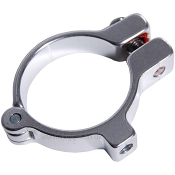
But I did stumble across these little gems. A couple of these would be ideal to mount the pivot block.
$19 http://www.hfutmpa.com/product_PROBLEM-SOLVERS-ECLAMPS.html, or
$19 http://sellerby.com/good_7588_457359832-PROBLEM-SOLVERS-E-CLAMPS.htm
FD307Z01BLK__114.jpg


Or even cheaper.
$5.50 http://www.chainreactioncycles.com/Models.aspx?ModelID=745
$4.10 http://www.wiggle.co.uk/p/cycle/7/DMR_Hinged_Clamps/5220000003/
dmr-hinged-clamp-med.jpg


Now i just need to spend a bit more at wiggle to get free shipping :D

- Adrian
 
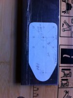
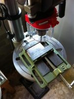
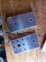
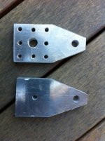
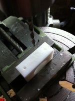
Finally started cutting metal. :D
- Angle grinder to cut the 10mm plate to size.
- Drill press to make the holes.

Will get the shaft support bearing hole done properly at work.

I'll pretty it up once I do my first dry fit.

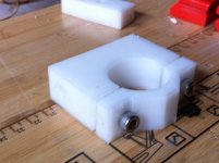
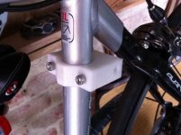
CBv1_1.jpgCBv1_2.jpgCBv1_3.jpgCBv1_4.jpg

- Adrian
 
Kepler said:
Well its going to strong being made from 10mm Ali thats for sure. I use 4mm Ali on my swing arms but I do need to make separate flanged bosses to hold the pivot shaft.

:D No point skimping on the first prototype.

Update:

One of the annoying things about this build is that the shaft pokes out the wrong side of the motor for my needs.
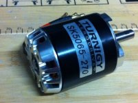
To move the shaft requires a little bit of effort. For the little TGY AerodriveXp 90 SK Series 50-65 270Kv / 2100W this requires you to:

1 ) Get a replacement shaft with a circlip groove in at the end of the shaft.
Turnigy AerodriveXp 50-65 SK Series Shaft US$5.12
Or machine the groove in the original if you have access to a lathe.

2 ) Remove the circlip & washer
View attachment 4
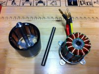
3 ) Carefully pull the motor apart (note new shaft in centre of image)
IMG_1163.JPG
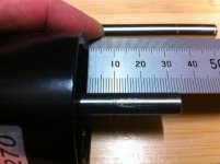
4 ) Measure shaft circlip groove location
- when putting th new shaft in it is important to have this groove in the same location.
IMG_1164.JPG
5 ) Undo the two shaft retaining grub screws
- GOTCHA #1: Make sure you remove both grub screws. I forgot and stuffed a motor because of it :roll:
- GOTCHA #2: The grub screws on my first motor used metric alan keys, the second motor uses something else. :x
[EDIT] Correction: it does use a 1.5mm allen key, just make sure it is a good one without crappy rounded edges. :roll:

View attachment 2
6 ) Press shaft out
- the shaft has an interfernce fit so will need to be pressed out.
- remember make sure both grub screws out removed, before pressing the shaft out.
IMG_1166.JPG

7 ) Press new shaft in to correct location
8 ) Replace grub screws
9 ) Reassemble motor
10 ) Replace circlip with washer

This will put the motor shaft out the other end, which allows the second pivot arm to support the motor via a bearing.
 
adrian_sm said:
One of the annoying things about this build is that the shaft pokes out the wrong side of the motor for my needs.
To move the shaft requires a little bit of effort. this requires you to:

1 ) Get a replacement shaft with a circlip groove in at the end of the shaft.
Or machine the groove in the original if you have access to a lathe.
......

OR... you could just forget the circlip all together since this is not a axial loaded application, (like a prop pulling ?)..just supporting the motor .
The grub screws will keep the shaft located in this type of install . :wink:

:shock: Hey, wow, one mighty clean workmate ! :lol:
 
After I have been cutting and grinding on one of these shafts, I am certain it would not be difficult to cut a new circlip groove where ever you needed. Perhaps put the shaft in a drill-press chuck to spin it slowly, and then hold up a hack-saw blade to the spot where you needed the groove?

Make sure to hold the blade so that if the blade gets grabbed and moved, that it is pulled away from you instead of stabbing your hand. I strongly suggest wearing a glove...I have many scars from when I did not wear a glove.
 
Hillhater said:
OR... you could just forget the circlip all together since this is not a axial loaded application, (like a prop pulling ?)..just supporting the motor .
The grub screws will keep the shaft located in this type of install . :wink:
I was just worried that if I didn't have the alignment just right, there might be an angle between the motor, and tyre. This could try and drive the motor can axially when loaded up.

spinningmagnets said:
After I have been cutting and grinding on one of these shafts, I am certain it would not be difficult to cut a new circlip groove where ever you needed. Perhaps put the shaft in a drill-press chuck to spin it slowly, and then hold up a hack-saw blade to the spot where you needed the groove?

Make sure to hold the blade so that if the blade gets grabbed and moved, that it is pulled away from you instead of stabbing your hand. I strongly suggest wearing a glove...I have many scars from when I did not wear a glove.

Hmmm there's an idea.

You might even be able to just cut the groove without removing the shaft at all. Just bolt the motor down, spin it up, the cut the groove with the hack saw blade...

The main reason I didn't modify the original shaft was that I needed a second shaft for the main pivot anyway. The idea being that you reuse the motor shaft for the main pivot, and then use the new, readily available hobbyking shaft with the groove in the right spot for the motor.

This means anyone copying my design doesn't need to bother modify the shafts. Too easy. :D
 
I just checked Fastenal's catalogue, and those shaft grub screws for the 50mm diameter motor are 'likely' to be M3-0.5 threads, since they are using the 1.5mm hex-wrench.
http://www.fastenal.com/web/products/detail.ex?sku=40818&ucst=t

That means if you took it out and wanted to just use a common socket-head bolt with a dab of loctite, the hex-wrench would be a bigger 2.5mm wrench, MUCH better. I don't know if that would cause an out-of-balance condition, so I won't throw away the grub-screw until I see if it works.

I noticed on the new 280-kV motor I just got, that the motor-shell screws (for the skirt bearing) are flush-head hex-sockets instead of the philips-head screws on the 250-kV motor I got a month ago. They use a 2mm hex-wrench. I hope they start using hex-sockets for all their fasteners.

Edit: just pulled out the shaft grub-screws on my Turnigy 63mm motors, the 250-kV and the 280-kV, there are two each, so no out-of-balance issue. The hex-wrench is a 2mm, and the diameter is 3.92mm, so they are likely M4-0.7mm, and could be replaced with cap-bolts that use a 3mm hex-wrench. I will check my local bolt supplier to verify.
 
Update:

1) Motor Shaft
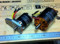
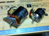
Photo of the new shaft installed in the correct location.

This will allow the motor to be supported on both sides.
On the mounting side with 4 screws, on the opposite side by a bearing in the pivot arm, supporting the shaft now that it protrudes.

IMG_1172.JPG

2) Pivot Arm Bearing
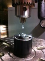
Took that shaft support pivot arm to work to get the bearing mount machined. Still waiting on it.
I might just do it my self, with a 22mm hole saw and some lubricatant on the drill press.
If the size isn't quite right, I'll just loctite it in place.

If that works, the only tools anyone would need to replicate the design would be:
- angle grinder with cut-off disc to cut the aluminium plate to size (or hack saw if you are really patient)
- drill press & drill bits, to drill nice perpendicular holes (or handheld drill if you skills are better than mine)
- screw-drivers, allen keys
- M3 or M4 tap set, for grub screws in pivot arms to pivot shaft.

Next:
- pivot arm bearing mount
- waiting on seat-tube clamps to arrive
- make main pivot block to suit new seat-tube clamps
- sort out dead-stops, and springs
- ....
 
adrian_sm, I have recently tried a "nutsert" steel-thread connector, and I am very pleased with them.

I have been tapping threads into aluminum with a large 5-16"-18 tap, but for a smaller hole, I was very nervous, because I have broken taps inside holes that I needed and could not move to another spot. Hillhater reminded me about nutserts, and I tried a 1/4"-20, and it was very easy. Just drill a hole, do a dry fit to see if the location is perfect, then pull it out and use a smear of JB / Devcon epoxy-glue.

http://endless-sphere.com/forums/viewtopic.php?f=28&t=21365&p=326424#p323450

file.php
 
Nutserts are great for sheet metal. Use them all the time at work. Almost used them on my first ebike to mount the batteries in the frame.

Not sure where you thought they would help on this drive. But I am aiming for a simple easy to install, bolt on type drive. Hence the seat-tube clamps.

The threaded holes I referred to in the previous post, are at right angles to the main pivot shaft for grub screws. This will hopefully keep the two arms aligned with each other. That was one of the reasons I went for 10mm thick plate arms.

- Adrian
 
Have you considered just making the clamp integral to the pivot block as it is looking like a machined part anyway ?
just bore it to suit the downtube dia, (looks like you are half way done anyway ?) .. split it, and use 2 clamp bolts.
 
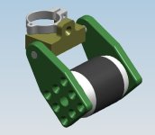
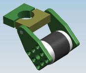
Hmmm looking at the CAD image above, I don't know why I don't just do this.
Probably easier, cheaper and stronger than the seperate OEM clamp.

friction_drive_ver5_turnigy_50_65_270kv.PNG
 
Hillhater said:
Have you considered just making the clamp integral to the pivot block as it is looking like a machined part anyway ?
just bore it to suit the downtube dia, (looks like you are half way done anyway ?) .. split it, and use 2 clamp bolts.

:D Missed your post while I was busy updating cad. Was bloody obvious once I saw it. Hopefully I can find some time this long weekend, an extract myself from the kids long enough to do it.
:D
 
Back
Top