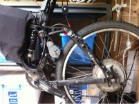
Commuter Booster - <1kg Friction Drive

BrainBox Update:

The button throtle, 8x2 LCD BrainBox with datalogging and temp sensor is all up and running, and working like a champ. But it has highlighted a few minor things I would like to resolve.

1) Wheel Sensor
- The current design places the wheels sensor at the rear wheel
- Fine for road bikes with narrow frames, but not good for MTBs with wide frames as the sensor needs to be spaced out to see the magnet
- So do I add wire length to route it to the front, or rely on people spacing out the sensor if needed?

2) LCD Contrast
- I used to be able to ground the contrast to get the right LCD constrast, but my new supplier's LCDs require ~1.0v to get the contrast right
- This means (a) I need to add a pot and adjust it for each screen, (b) it upsets the contrast depending on whether the BB is powered via the ESC or USB. : (

3) LCD Display
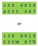
- Currently I have the display showing; current speed, Distance travelled, and battery fuel gauge as a horizontal bar graph. (top image below) All other stats can be scrolled through while at rest, with the battery gauge always displayed (see rest of images)
- This is great for fuss free riding, but occasionally I find I would like to see other stats while riding. The issue is screen realestate.
BB-display-v1a.png
- I am thinking of changing the top line to be speed & battery percentage, then use the bottom line for a user selectable stats from: power, amps, volts, wh/km, average power, dist remaining, distance travelled, trip time, wh used, temperature, Total Kms, Total Time, Total kWh, etc.
- Then which ever stat is selected remains on the bottom line during the ride.
- To change the stat you would need to perform a momentary button press from zero power, either at rest, or during the ride by powering off, doing a quick button press, then getting back on the power
BB-display-v2.png

4) Wiring Layout
- Currently everything is hardwired that can be, requiring the following to be connected:
---- power inline sensor between battery and ESC
---- ESC throttle
---- Temp sensor
- The battery and ESC currently form a sort of package on its own when installed
- This means if you want to remove the battery, you need to disconnect quite a few things. I charge the battery on the bike so it isn't an issue for me, but it may annoy others.
- I need to look at all the possible layouts, and locations of various components to see which is the best compromise again. I think something that allows you to quickly remove the battery, leaving everything else attached to the bike would probably be desireable. But that would probably require seperately mounting the ESC, and possibly mounting the uC, SD, and USB connection in the main LCD enclosure. Which is very difficult for the 8x2 enclosure I selected, but possible for the 16x2. It just makes weather proofing more difficult while keeping access to the SD card and possibly the USB connection.
- I need to resolve weather proofing in general so perhaps I should just solve both these issues at once, by mounting the ESC, uC, SD, USB all in an aluminium enclosure like the hammond boxes, or in a plastic enclsoure like my v1 BrainBox.

So everything is functional and robust, but it still needs a little bit of tweaking before release.

- Adrian

P.S. I am seriously considering removing the SD datalogging, as it takes up 1/3rd of the programming space, I am hitting SRAM limits, it is stopping me from implementing a few things I would like to, and most average users won't ever use it. But I know the ES crowd will love it, as it essentially automatically records real time & summary data for every trip you take.
 
Hey Adrian,

good to hear the progress! I hope you're having fun, with it so close to completion.

My two cents:
1) Youve got wiring to the front already hey, for the display? It might not be too much more hastle to have another pair for the wheel sensor? Would the extra length be subject to interference though?
2) I reckon a lot of developers deal with this sort of issue by presenting it as a "feature": user-settable contrast! It doesnt suit the beaut design simplicity of this concept, but you'd get away with it. And an extra pot is surely cheaper than a 1v regulator?
3) Would this be something you could offer the user to switch between via the USB set up? I like the barplot rather than another row of text, but I'm not everyone. (Would you consider adding a second button? There is so much functionality now, I wonder whether you're hindering usability a little by sticking to the single-button simplicity?)
4) Personally I'd like to be able to charge off the bike. If easy-removal of the battery is possible, that'd be great. Second most best thing to be able to remove would be the motor. I'd be very happy to leave the wiring loom attached, with ESC and BB etc. Whether they'd be in the same enclosure, I wouldn't mind.
Yes, I guess there'd be some gnashing of teeth if you removed the data logging, but then, if you're going for a larger market than stats geeks, it probably makes sense doesnt it.

Good skills bro, and I hope I'm still on your list!

Eric
 
Hi Adrian,

Some comments about the different points :

1) I think it is not very complicated to space out the speed sensor. And it allows to see the no load speed.

2) For me it's important to have the correct contrast when the brainbox is mounted on the bike, so powered by the ESC. The brainbox is powered by USB only during programming, isn't it? So I think it is not dramatic if the contrast is not optimal.

3) For me, the ideal would be to see speed, battery voltage (or battery percentage), power and distance, as shown below :

BB.JPG
How does the fuel gauge work? Do you enter the battery capacity as a parameter? Or is it calculated with the battery voltage?
To see other parameters, I think your solution is perfect.

4) I use my bike to go to work. I let the bike in the parking and I charge in the office, so I have to disconnect the battery. I don't understant why you say "the battery and ESC currently form a sort of package". Because of the power sensor? Or because of weather proofing ?
If you mount the ESC, uC, SD, USB all in an aluminium enclosure, it means the motor wires will go from the handlebar to the motor?
And concerning the SD datalogging, as you say I think I won't ever use it, or only the first time to test it.

Eric
 
Thanks for the comments guys. It helps.

I have been spending my time exploring and building various variants of the hardware for the Brain Box. Weather proofing and easily removable battery has been quite a challenge to resolve. So far I have been using the battery bag as my way of weather proofing the brain box, by tuck it away inside. But if you want to uickly remvoe the battery, this isn't an option without a connector to make that quick. And it is already taking me way too long to assemble these units with a lot of fiddly soldering, so adding a bunch of extra soldering for a connector is not a great option.

So what have I come up with. This:

(1) Basic Brain Box
This is what I am thinking of as the default interface for my friction drive. It has no display, and is programmed via USB and a terminal program on PC/MAC.
It allows people to attach any ESC they like, is all housed in a weather proof box. Plug'n'play type design, stripped down to the essentials.
- connects in between battery and controller on battery leads
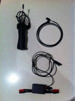
- throttle in (hall, pot or button)
- throttle out to ESC
- wheel sensor (with wires long enough to reach either wheel)
- two code options
-- closed source CB code, for button throttle, PID power&speed control, cruise control, min.max speeds, downloadable trip & life stats via USB
-- open source generic throttle interface. provides basic throttle mapping to start with, but obivously has access voltage, current, speed inputs. Can be expanded with other iouts too such as temperature sensors, more buttons, switches.
Notes:
- this could also be used as a throttle interface for any ebike. Allowing any type of throttle input, and custom throttle profiles
- this would be based on the Arduino Nano, which includes a USB port that allows very easy conection to a computer if reprogramming is required.
CB-BB_Basic.jpg

(2) Standard Brain Box
- similar to the Basic, but adds a 8x2 LCD. Programmed via LCD now, and remove USB programming.
- This gives you the usual Cycle Analyst type stats, plus a few extras. But still lacks SD datalogging, or temp sensor input.
- For me to keep the current 8x2 enclosure I have been using I would have to change to an Arduino Mini Pro, which losses the USB port, so this would make it a lot harder for people to reprogram it if required.
- Or I could go to a 16x2 display, keep the Arduino Nano and handy USB port.

Optional Extras:
These are things that I have implemented, but are just taking too much time for me to wire up without a custom PCB to make life simpler. So for now they are not being included by default. I am not sure how I will handle it in the future, it depends on the feedback I get. Perhaps I could have the code implemented to handle them, and let people wire it up themselves. Don't know.
- SD datalogging
-- This is a cool feature but one that in normal usage is rarely used. So I am not sure people would pay a premium for it.
-- It currently automatically records trip stats summary, and a separate file that logs settings, and real time data
- Temp sensor
-- again this is easy to implement, but just another wire hanging out that most people wont use.

The people that will want these features are those that are stats nerds, or those pushing the limits of there drives. As you can log all the throttle, power, volts, amps, speeds, temps you could desire. It has been a really useful tool for my development of the drive, and to understand how different motor behave, but most people just wont use them. The other nice thing is that it can automatically log trip stats without any intervention. So you could just pull the files once a month, year whatever, and check out battery usage, efficiencies, volts, wh, etc.

(3) DIY Kit
An option to get around the high labour component of me making these in prototype form, would be for me to supply a complete kit with all required parts, preprogrammed, and allow people to assemble it themselves. It would allow people to wire it up exactly how they like. So they could make it a fully integrated package, or easily removable, or take advantage of any weather proof enclosures they have elsewhere on their bike. Add connectors where they like, or hardwire the whole lot.

(4) The complete package
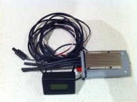
This is my ideal solution. It has the ESC & brain box in one weather proof package, which is the goal for supplying a complete package. Just plug in the battery, connect the pahse wires out, and strap on to the bike and your away. But...... it is a nightmare to make so I was happy to do it once for myself, but I would not be able to do this for others as it takes too way much time. If I got a custom PCB made I might be able to make this more realistic, but I am not there yet.
- on/off switch
- battery leads in, phase wires out
- throttle in (hall,pot, or button)
- temp sensor connector
- micro SD card
- wheel sensor (with wires long enough to reach either wheel)
- 8x2 LCD display
- custom closed-source code with all bells and whistles, ebike stats, temp sensor, data logging, PID power & speed control, min/max speeds, ....

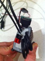
Anyway here are a few pics of the Complete Package.
CB-BB_Complete_3.jpgView attachment 1CB-BB_Complete_1.jpg

P.S. The battery gauge at the moment is based off of wh used, relative to capacity entered. Battery voltage is too rough especially with voltage sag making it difficult underload.
 
I must have about 6-8 different physical varients of the Brain Box now. :roll: Latest varients are both non-SD versions. One with a 8x2LCD with uC all in the same enclosure, but with an additional momentary button on the side. Thinking was to use it for all the display options, and leave the throttle to just be a throttle. This will make swapping to an analog throttle much easier. It also frees up some much needed memory to implement a few things, and make a switch to a 16x2 LCDLCD easy.

Other varient has no display. So only a throttle cable (and possibly wheel sensor) runs up to the front. Very minimalist.

In other news .......

friction_drive_plus_hub_wtf.jpg

:D
 
The bike is mine. It's my hub motor dual suspension bike. :D

Really not keen on having to wire up more stuff so doubt I would ever go to a second uC. Hopefully when I get time to clean up the code, space may not be an issue. Adding the second button may actually simplify the code too since it is easier to differentiate what button presses mean.

[EDIT: Fixed typo]
 
Nah. :lol: actual plan is a poor mans dyno. It will allow me to compare motors more accurately.

I was thinking of using the controllers regen and a spare BrainBox to do data logging. I haven't had a real chance to play with it yet, but I was surprised at how much power it took just to spin the wheel with no regen. So the plan of just measuring the current going back in to the battery to be a real measure of the power output of the Commuter Booster appears to be flawed. Ah well.
 
:eek: Not everything works first time, and some things never work, but you have to try ideas else you stagnate.

Going back to your memory problems for a bit (as in the µC's, not your's), have you gone through the code and used the smallest variable types possible (bytes instead of ints, ints instead of longs, longs instead of floats / doubles etc) where applicable? Just asking.
 
Yep. More of an issue with SRAM space, which is more challenging to track down since it heavily depends on the SD library, which I can't be bothered further optimising code I am not familiar with. I was also at the limit of program memory at the same time so that made things fun to debug. It is all working now even with SD data logging, but doesn't leave room to try out new things without running in to problems.

So for now I'll branch the code, drop SD support, and streamline the more fundamental features. Then I can bring back the SD code later.
 
:D
Hello Adrian and company, I have read the entire forum, and I have to give enorabuena for your work and have encouraged me to make one.

As Hobby King is exhausted Brushless motor Outrunner HXT 63-74 200kV, I thought this Pener Aerodrive Pener SK3 - 6374-149kv Outrunner Brushless Motor
[urlhttp://www.hobbyking.com/hobbyking/store/__18184__Turnigy_Aerodrive_SK3_6374_149kv_Brushless_Outrunner_Motor.html][/url]

But I worry about the axis of 8 mm for a single arm.

Also I think this esc HobbyKing Red Brick 125A ESC [urlhttp://www.hobbyking.com/hobbyking/store/__18014__HobbyKing_Red_Brick_125A_ESC_Opto_.html][/url] would be good, as would be over sizing to avoid high temperatures, two cosets is copletaria how are you in pararelo batteries ZIPPY Flightmax 8000mAh 6S1P 30C
[urlhttp://www.hobbyking.com/hobbyking/store/__16228__ZIPPY_Flightmax_8000mAh_6S1P_30C_.html][/url] how are you and I want a range of about 40 50 km, and other material that you advised.

Thanks again for your work and do while waiting for your answer.

Note I apologize for writing since I made ​​the translation with Google
 
Welcome Juan,

Thanks for the kind words.

I have been testing a wide range of motors recently, including some of the SK3 motors. The 8mm shaft should be fine as the skirt bearing takes a lot of the load off this shaft.

Here are some of my notes from the SK3's
- bearing quality was good
- fit and finish good
- relatively low levels of flux leakage
- motor diameters smaller than the old orange turnigy 6374-200kv
- a bit noisier on the bike with higher frequency tone than the old orange turnigy 6374-200kv
- cooling holes in the can may be an issue, as they closely align to the edge of the tire on the commuter booster, therefore may allow sand etc picked up by the tyre to enter motor.
- greater radial clearance is required on motor swing arm to accomodate shaft retention clip of SK3 motor

The 149kv motor on 6s LiPo should have a no load speed of ~40kph, so you will end up cruise on the flat at ~35-36kph. If you want faster go for the 168 or 192kV motors.

As for the ESC you linked to, I have never tried it so can't comment. But generally picking one that can accomodate high voltage & higher current than you expect is always a good.

General comment on selecting an ESC based on my preferences are:
- I like them with an on/off switch, so I don't have to disonnect the main battery cables very often. That is the main reason I like the Turnigy Brushless ESC 85A w/ 5A SBEC.
- the friction drives prefer to have the throttle slowly increased. Some ESCs have a soft start option that can do this well. Others don't. I have ended up designing and manufacturing a custom throttle interface/bike computer that does this among other things. But a simple solution is to use one of these which can adjsut the ramp up speeds, Turnigy 3 Channel Servo Speed/Direction Regulator
- the ESCs also don't like low speed, high torque situations, so be careful use the drive a slower than walking pace.

Finally the friction drives in general work best when power is restricted, so either be careful with how you apply the throttle, or expect lower efficiency or tire wear.

Batteries capacity. This really depends on a lot of factors. I personally do most of my riding with the commuter booster on a good road bike, and like to pedal. I generally cruise at ~40kph, and usually see efficiencies of 6-7wh/km. But if I didn't pedal much and was on a mountain bike, I would likely see up around 10-12wh/km for similar speeds. So unless you like to pedal quite a bit, and don't mind running your battery flat every ride, I would recommend a larger battery if you plan on 50km trips regularly.

Another battery consideration is how you plan to put them on the bike. I actually prefer to use four 5s5Ah batteries, as I can fit them in my Topeak Aerowedge saddle bag. But I can only fit three 6s5Ah batteries in the same bag, which does not give me as much battery capacity. This means I typically would use the 190-200kv 63mm motor to get the speed I like, where as if I had the 6s batteries I could probably use a 170kv 63mm motor instead. So make sure you have a plan on how you will mount the batteries to your bike before you buy them.

All the best,

Adrian.

P.S. I will be posting soon about my next manufacturing run of both Commuter Booster Drives, and my new electronics interface that will soon be for sale. :D
 
Hello Adrian,

Do you know if you kit would fit a small bike such as a Brompton (need a bike easy to carry on the train) and be able to reach 50 km/h?

Thanks a lot
 
Not out of the box.

Ltype.jpg


It looks like there would be enough room in or below the rear triangle, but would require a custom designed pivot block.
 
You got me curious about the brompton and how hard it would be to mount my drive on it so I searched a bit more.

Hmm and looking a bit closer it looks like the space I would usually mount my drive is occupied when the bike is folded. So it may rule out mounting a Commuter Booster in there. :( Unless you feel like carrying an allen key and taking the drive on and off each time you fold.

eazy-wheels-04-485.jpg


Oh, and here is a better pic of the rear triangle. It is obviously missing the seat tube that I usually mount the drive too. Hence the need for a custom solution...

6157995230_071d4bc4f4.jpg


- Adrian
 
Would that work better with a Dahon Uno?
dahonfiets.jpg


Or I can just unmount the kit everytime I fold the bike if it's fast enough. (I mean no more than 1 mn)

Actually, the bike doesn't matter because I haven't purchased it yet. I could get any as long as I can easily carry it on bus/train and that goes fast.

Looking forward to buy your kit Adrian!! :lol:
 
Ah cool. Then you might be interested in ferias77's build. He made a drive based on my design and got it all setup on this little folder.
http://endless-sphere.com/forums/viewtopic.php?f=28&t=31457&p=487824
biketb.jpg


Last I heard he was having a few issues with drive engagement, but since this is not one of my drives I am not totally sure what the issue was. You can see the discussion on his thread.

I know Kepler also has one of his eBoost drives on a folder that works a treat. His design mounts the whole drive unit on the seat post (rather than the seat tube like mine), and is designed more around quick installation/removal so that might be a better option depending on the bike you end up with.

P.S. I am getting ready now to put the beta drive units up for sale. I am just waiting on receiving some parts, and cleaning up the firmware based on all the testing we have been conducting over the last few months. I will post something more official soon. Sorry to everyone that has been wanting a drive but I would really prefer to get this all debugged and right before I make people give me their hard earned money for it.
 
Thanks for your answer Adrian.

This is a very nice build from Ferias. Definitely worth considering if the tyres don't die so quickly and if the controller was still alive. Waiting to know what was the problem.

I also was under the impression that friction drives are quite loud:
http://www.youtube.com/watch?v=61sM9qovORU&feature=related

If we have to compare with Direct drive motors, how much louder it is? (I just want to be as stealthy as possible :lol: )
 
If you want a real quiet drive, go for a hub motor. Direct drive hubs tend to be the quietest, then geared hubs, then RC drives. This is just from my personal experience. I am sure others will have different opinions. But the hubs are obviously a bit heavier for similar power.

RC drives have less mass to dampen out the noise, and run higher RPMs which means higher frequency noise which the human ear perceives as loader. Exactly how load they are depends on a heap of things, which motor, what load the motor is under, how it is mechanically couple to the frame, ESC settings... and so on.

But picking a good motor, and reducing the power goes a long way to keeping the sound at a reasonable level. It is one of the reasons I have spent so much time recently developing my throttle interface/bike computer/brain box thing. It nicely controls the power to the motor, which keeps it quiet. Not as quiet as a hub motor, but quiet enough for me.
 
As long as it's not too noisy, that should be fine. By the way, have you tried to surround your kit with sound isolation foam? Not sure if that is useful at all.

Also, from my other post I tried to compare the efficiency of the commuter booster to a hub motor, here is what I found:

If I reach 30 mph (50kph) on an Ezee 20" I need 90V:
Ezee_speed.jpg

http://ebike.ca/simulator/

For that, I'll consume around 30 Wh/km


Here is a comparison to a RC motor (friction drive):
eBike%252520-%252520Economy%252520vs%252520Speed.PNG

https://sites.google.com/site/commuterbooster/performance

I'll consume around 15 Wh/km

Please correct me if I'm wrong, but can we say that the commuter booster is 2 times more efficient than bike motors?
 
No it is not more efficient,the setups/assumptions are different.

The ebikes.ca calculator is pessimistic assuming no pedaling, and a crappy bike. The CB stats were based on an efficient road bike and used as an assist.

My system gets the efficiencies from:
- totally disengaging and having no drag when not in use
- minimizing additional weight
- allowing the use of high quality and efficient bikes components like low rolling resistant tires, aero bike, light weight components, etc.

So it is not really comparing apples to apples. If you did have the same assumptions the efficIency numbers would look very similar. There is nothing magic about my drive that breaks the fundamental laws of physics. :D

As for sound deadening, no I haven't tried that and i would bet it wouldnt work.

If you want an ultimately quiet drive don't get one based on a small RC motor. Get a hub motor.
 
Hi and welcome to ES.

Have you got more details? Did you measure motor temperatures before and after the fan being added?

I have always thought they would not work very well as they will provide no cooling to the motor coils on the other side of the motor. But I have never tried it so would love to gear your experiences.

- Adrian
 
Back
Top