Commuter Booster - <1kg Friction Drive

Do you have much problems with dust and a bare motor? Without reading through all your posts, which materials have you found not super abrasive but still capable of providing adequate grip for dust and moisture conditions?

to me some slippage is okay. I think a little tire wear is okay, too. I'm sure the abrasive wrapped motors are more peppy than none wrapped ones--but at a cost. Where's the best of both worlds?
 
I always run my drives bare motor on tire, but rarely ride in the rain. And I don't recommend the drive for wet weather riding anyway. But when I do ride it in the wet I just swap motors for one that I have wrapped with the grip tape.

As for dusty conditions, it is no issue for getting power from motor to tire, or tire wear. But it does cause wear of the motor outer casing. I only really noticed this when riding continuously on unsealed trails.

This drive is a compromise, and best suited to riding on the roads in dry conditions. In those conditions it is by far my favorite ebike. But I am not exactly an impartial reviewer now am I...
 
The drive is excellent in the dry !
I also use the bare motor and will not be putting any grip tape since we don't get so many rainy days here in Greece.
As for dust, the only thing I noticed is that it increases grip of the motor to the tire boosting up the power transfered (maybe because my setup is not perfect and I get a little slippage on the tire). There is wear on the motor surface but not much and the tire is still fine.

By the way, Adrian

I was riding the bike the other day and I started my ride with a voltage of 19.5 and ended the ride with a voltage of 18.4 (5S lipo pack). All was fine but then I noticed that the brainbox reported a minimum voltage of 14.7 during the ride. Is that normal or is it bad for the batteries? I balance charged them after the ride and both packs were fine.
 
Thanks for the feedback from the real world. Always appreciated.

As for the 14.7v minimum voltage, it sounds about right as you will see it sag underload especially when you are at the end of the pack capacity (18.4v/5 = 3.68v which is pretty much empty). As long as the at rest voltage is acceptable your battereies will be fine. The ESC should cut out from its LVC tripping to protect your pack anyway, so don't be concerned.
 
Just because I'm really impatient and need a hand up some hills 8) if anyone is looking at selling one of these please let me know (yes, I know it's a very slim chance) :lol:
 
Hey Adrian,

It's a good thing I found this thread. When do you expect this next group of testing to be sorted? I'm just really aching to give you some money so I can finish my commuting project please. :)

I'm in Collingwood too so if I can get in on testing units man I'd love to be part of that too.
 
Hi Everyone.

Sorry about the slow reply, but sort of on enforced holiday from this project for the last month or two unfortunately. But will be back in to it next week.

Good news is I have the final few contenders for controllers in my hands ready to test, so should resolve the ESC selection soon. This will allow me to finalise the electronics design, and decide on the system voltage, and allow my battery manufacturer to finally send me out the samples. While I wait for those I'll update the mech design, and press the go button to get the next batch made.

All my bench testing is really letting me understand the limits of each component in the electrical system, and will make for a much more robust design.

- Adrian
 
You have take the electric motor in a whole new direction. The problem has always been, too big and too heavy. I look forward to new developments.
 
I have been reading through your threads again and I did want to make a suggestion.

Have you thought of putting in a port for connection to Methods Lipo battery protection boards?

This would be a great "plug and play" way to safely connect to up to eight 6s packs with the addition of one board. I imagine this would be especially helpful if you do go ahead and package the kit with a charger.

adrian_sm said:
Hi Everyone.

Sorry about the slow reply, but sort of on enforced holiday from this project for the last month or two unfortunately. But will be back in to it next week.

Good news is I have the final few contenders for controllers in my hands ready to test, so should resolve the ESC selection soon. This will allow me to finalise the electronics design, and decide on the system voltage, and allow my battery manufacturer to finally send me out the samples. While I wait for those I'll update the mech design, and press the go button to get the next batch made.

All my bench testing is really letting me understand the limits of each component in the electrical system, and will make for a much more robust design.

- Adrian
 
Interesting idea. The beta kits that I sold relied on the pack level LVC of the controller, but for those that want to go to cell level, methods boards could work nicely.

In the future I am actually planning on providing a complete battery pack including BMS, so won't have a need for it.

- Adrian
 
Hey everyone. I have totally sold out of the last batch I made, and in the process of redesigning things for the next batch. In fact I am in the designing some custom PCBs right now.

I have now spent a huge amount of time pushing all the electronics to the limit, so I really understand the system and what it can handle. This has helped me select each component with confidence, and also meant a significant update to the way the electronics work to help self protect everything. From a user perspective it probably won't feel that different, but it will now be able to hit long haul climbs with confidence.

This time around I will also be providing the drive including motor, and controller all as one package. So no stuffing around to buy all the other bits an pieces. I have a few options on batteries and chargers, so do plan on selling a complete kit if that all goes to plan.

The bad news is that I have less free time to focus on this now, so I am not making promises on the next release date. Apart from promising that it will be available when I am happy that it is ready, and not before.

Finally thanks to everyone for there interest and patience. I have been amazed at the huge interest this design has generated, and I am doing my best to make it available.

- Adrian
 
Okay I am debating what features my new control PCB will have, so I thought I would document it here so others can give me their opinions.

So I am making a custom PCB to do all the smart control of the RC ESC. Including:
- power limitting
- throttle interface
- throttle ramp rate control for smooth drive ngagemnt/disengagement
- CA style display
- EU/AU/US legal modes etc.

What I am debating at the moment is whether I implement a soft on/off switch. The idea is that the bike will put itself to sleep when the speed/throttle hasn't changed for xx mins. Then you just press a button to wake it up. The main purpose is to protect the batteries from idle currents, as most RC ESCs and the controller I plan on using do not have an on/off switch, so the only option to turn it off is to physcially disconnect the battery.

So how much current are we talking about:
- YEP 150Amp ESC = 10 mA
- Tz85Amp ESC = 50 mA
- Current Generation Brain Box = 30mA

So @ 40mA * 24 hours = ~1Ah in a day. :shock: Not good

Option 1
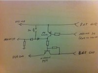
Originally I had planned a soft on/off based on this circuit. Which worked nicely with the low power on/off switch of the Tz85A ESC.
attachment.php


But now that I have no on/off switch on the YEP 150Amp ESC, I have to cut the main power. So rather than a little transistors I have to have bigger FETs I guess. These will have to be able to handle 500-1000w at 5-6s, so lets say 50 amp continuous. But the power flows through the p-channel transistor, which in FET land means high Rds-on. In the order of 10+ mOhm. :(

That won't work. So I need to modify the circuit to work with an n-channel fet cutting the power, so I can use a fet more like this.

Or.......

Option 2
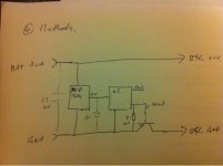
Go for something more like Methods Solid State Relay, but run the LDO straight off the main battery pack. A 24v capable LDO like the MCP1804 has a queiscent crrent of 150uA, and with some Arduino magic, we can get the uC current really low too.
file.php


So... I need to either modify Option 1 to have an n-channel fet to cut the power, while still allowiing my button state to be detected by my 5v arduino. Thus should result in having just the fet leakage current of 20uA to deal with.
Or... get fancy with my arduino and trust in Methods design before he has even prototyped it, and take up a few extra IOs from the arduino to drive the FETs.

So what do people think? Can someone smarter than me modify the Option schematic to suit my needs?
 
Here is my hack at Option 1 to suit my needs.
Would love some review/feedback.

[EDIT #1]
- missed a resistor inline with the switch to limit the voltage at the arduino IO to <5v
Option 1 - Soft On Off Switch.jpg
 
I don't think this will work. The arduino pin can only work over 0-5V. So I would need the top transistor, to be open when the arduino pin is floating upto 5V, and closed when the pin is pulled to ground.
This is while the battery voltage is up at 20-25V....

This strategy will take way too many parts...
 
Tending towards Option 2. This means I can nolonger use a standard Arduino board as the brains for my board, the two will be integrated.

So the basic plan is:
- use the MCP1804 LDO powered directly off the battery connections
- this powers the ATMega uC,
- the uC then controls the IRFS3004 FET/s on the -ve battery wire
- the uC is asleep until the button is pressed, then stays awake while in use, and goes to sleep after a period of inactivity.

To minimise power in while asleep I will need to follow some of the tips from here:
- http://www.rocketscream.com/blog/2011/07/04/lightweight-low-power-arduino-library/#more-651
- http://hackaday.com/2012/08/18/making-the-arduino-sleep-the-long-sleep/
- https://www.sparkfun.com/tutorials/309

This means I will probably lose the FTDI & USB connections, so reprogramming will have to be done via ISP pins, or by the display if installed.

Option 2 - Soft On Off Switch.jpg
I'll need to do a power budget to make sure the LDO's 150mA is enough. But I guess I can always use the ESCs BEC voltage to power hungry stuff.
 
Last fet was not logic level, here is a better choice:
http://www.irf.com/product-info/datasheets/data/irls3034-7ppbf.pdf
http://www.irf.com/product-info/datasheets/data/irls3034pbf.pdf

Also missed the TVS diode from my schematic.

Also worried about directly driving the fet from the uC pin. The pin isr ated to 40mA max. continuous I assume but apparently 85mA peak (according to methods) to charge the Qg~110-160nC gate. Maybe I should put in some gate resistance to keep things under control.
 
More on the TVS diode.

Summary of need for the TVS diode:
Source
methods said:
The very high power TVS diode will sink all the nasty current spikes that happen at connection and removal. Many folks overlook this options - and it is probably because they have seen many mosfets blow up in this configuration. The secret is the ultra high speed TVS diode that eats noise and shits happiness.

More on transient protection of MOSFETs, and correct selection of parts
Source
- The working voltage of the TVS diode (Vrwm) must exceed the worst case supply voltage
- the TVS clamp voltage (Vc) must be less than the minimum breakdown voltage of the mosfet under peak pulse current conditions
- for switching inductive loads a 1500w TVS is recommended


Okay so:
- Vrwm >> 6*4.2V = 25.2V
- Vc < 40V

Possilbe Parts:
Through-Hole
1.5KE27
1.5KE27A
LCE22A
LCE24A

Surface Mount
SMCJ22A
1.5SMC27A
 
How difficult would it be to include a PV panel to charge this? I've looked around the internets for info about PV and Li-Polymer but haven't found much. What I'm imagining is a large PV panel on the back of my bike and a DC-DC converter between the PV and the batteries. Do I need anything else?
 
No idea. But I don't think you would get enough continuous power out of the panel, without it being huge and creating too much drag.

Better to keep batteries on board, and charge it at the end of the trip via a PV setup.
 
adrian_sm said:
No idea. But I don't think you would get enough continuous power out of the panel, without it being huge and creating too much drag.

Better to keep batteries on board, and charge it at the end of the trip via a PV setup.

What I'm looking for, and maybe the commuter booster isn't right, though it seems the best bet that I've found so far, is a very light motor set up that will not be in use most of the time but will help me keep up a decent speed on hills. Charging the batteries at the end of the ride, while the simplest solution, isn't a possiblity in my case because I will be using my recumbent for multi-day touring where I often won't have access to electricity at the end of the day.

My bike does (or rather, very soon will have) a midsized tailbox and I would like to stick a bunch of flexible PV to this and use this to charge as I ride, thus the PV (or at least the tailbox it is stuck to) should imporve rather than hamper my areodynamics. I have room for somewhere around 100 W of solar panel, though, of course, at any one time only a half to a third of this will be at decent angle to catch much sun.

Since I only intend on using the motor 10% or less of the time that I am riding, I'm counting on the PV being enough to keep it charged, but I've never really played with PV before so I'm not really sure how to include it into a battery operated circuit.
 
This has nothing to do with my Commuter Booster, but shouldn't be too hard.

This is what google turned up for me:
http://www.batterystuff.com/solar-chargers/
 
Hello,

All threat read , ready to buy stuff on ebay . Thanks a lot for all the efort along these months/years by the comunity to reach this point . I wanted to add a final word on how to improve the friction of the drive.

It´s quite simple , just cut a piece of rubber from an old tire and stretch it till fits tight on the right place , can add glue under to avoid side movement. Im talking about the inner rubber , its elastic like a slingshot and will do the job . I would preffer a thicker rubber elastic but thats all that comes to my mind easy to find for everyone.

I hope that helped ,
Thanks.
 
Hi Adrian,

How did you go with your soft on/off switch?

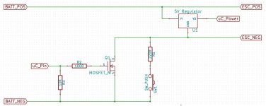
It should be possible to completely disconnect the batteries from the ESC and the uC and regulator. Here's a quick example:

E_bike_switch_2.jpg

The circuit works like this:
- Initially the mosfet is off and the ESC and uC are disconnected
- The user presses the pushbutton which turns on the ESC and uC ( R1 allows a small current to flow which charges the input capacitors of the ESC and then powers the standby current of the ESC and the uC )
- The uC waits a short period and then turns on the mosfet ( 5V on the gate )
- After the user has stopped pressing the button the uC can now control when it turns off by setting the gate of the mosfet to 0V
 
Back
Top