Confirmation/insight on battery build

dangol

10 µW
Joined
Aug 7, 2023
Messages
6
Location
Chicago
Hello all,
so I've been researching a decent amount, and have built up a battery thats 16s6p of Samsung 40t cells. I used copper+nickel sandwich technique to put a solid strip of copper across each series connection.

this has all been pretty straight forward, until now. I am at the point where I need to connect the BMS to the battery + and - main, but I am a little unsure of the wiring since this is my first attempt at ever doing this.

I couldn't really find any specific information that precisely addressed my concerns, so I took a screenshot from an ebikeschool video on youtube and then MSpaint edited it in order to try to demonstrate what I think is the correct way to wire things. Just wanted some confirmation (or denial!) of what I have so far. This is going to (ideally, if it's done correctly) be put into a stealth bomber clone with a 1500w hub motor

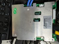
also as a sidenote, the bms in the drawing is actually how my bms is configured. It has 2 x B- and 2 x C-, but no P-, so I am guessing that it has to be wired the way it's shown there.

Thanks!

Battery wiring.png
 
That appears correct, though it does not show your cell-group sense/balance wires that are required for a typical BMS to do the job it's there for.

Which specific BMS do you have, and can you post a link to site it came from? (it may have further useful information)
 
When BMS is set up with separate charge and discharge ports, usually the discharge negative is labeled P-. The charge negative is labeled C-. Sometimes they're on opposite sides of the PCB.
 
That appears correct, though it does not show your cell-group sense/balance wires that are required for a typical BMS to do the job it's there for.
Yeah I just threw this together really quick and felt it might be a bit tedious to add those in in paint. also the battery pictured is actually a 10s, but the main + and - both end on the same side as my battery so the main idea works for illustration purposes. my balance wires have a b0 and then 1 through 16, and I planned to do the b0 to main negative, and then b1 to that same cell group positive, and then every positive after that gets the next higher number. does that sound correct? I haven't done any wiring yet besides the battery cells to each other with the copper nickel, but I have everything ready to go as soon as i feel more confident making this last few connections.
 
When BMS is set up with separate charge and discharge ports, usually the discharge negative is labeled P-. The charge negative is labeled C-. Sometimes they're on opposite sides of the PCB.
Mine just has 2 x 10awg wires coming from a B- pad and 2 x 10awg wires coming from a C- pad. No P- on the back or anywhere else on the board.
 

Attachments

  • PXL_20231218_192237631.jpg
    PXL_20231218_192237631.jpg
    2.5 MB · Views: 8
my balance wires have a b0 and then 1 through 16, and I planned to do the b0 to main negative, and then b1 to that same cell group positive, and then every positive after that gets the next higher number. does that sound correct?
Without a link to the sales page that might have more info, and/or a specific model number of BMS to perhaps find such info elsewhere, I can't tell you how it would be wired with any certainty.

Wiring it wrong can damage or destroy the BMS (or even just prevent it from working correctly) and it can be a completely silent failure, so you won't know anything is wrong until your cells are damaged or destroyed by the BMS being unable to perform it's functions to protect them.

I don't recall the typical BMS using anything other than the actual B- for the negative connection. The sense/balance wires usually go only to the cell positives, but there are exceptions.

If you have more sense wires than cells, there are specific ways they must be wired for it to operate, and that is different for each specific BMS; you have to get that info from the BMS manufacturer if it isn't provided by the seller and not found *for certain* from another source.
 
Mine just has 2 x 10awg wires coming from a B- pad and 2 x 10awg wires coming from a C- pad. No P- on the back or anywhere else on the board.

Your picture tells you the manufacturer, p/n, and type of BMS, which you can use to find it's wiring diagram:
1702931035668.png

JBD Smart BMS 16S 17S 20S 24S 60A 80A 100A 48V Lithium Battery PCB for Freeshipping - Jiabaida BMS It has connection diagrams, etc, such as this one
1702931451367.png

Since it's a Smart BMS you'll also need to connect to it from a computer (via the UART or RS485 ports) to set it up for your specific pack and usage, if the factory defaults don't match those. If you have the BT module you can use their app instead. Some of their pages link the software on them, this one doesn't, so you will have to ask them directly for the software to use for this specific version of this specific BMS.
 
Your picture tells you the manufacturer, p/n, and type of BMS, which you can use to find it's wiring diagram:
View attachment 344615

JBD Smart BMS 16S 17S 20S 24S 60A 80A 100A 48V Lithium Battery PCB for Freeshipping - Jiabaida BMS It has connection diagrams, etc, such as this one
View attachment 344616

Since it's a Smart BMS you'll also need to connect to it from a computer (via the UART or RS485 ports) to set it up for your specific pack and usage, if the factory defaults don't match those. If you have the BT module you can use their app instead. Some of their pages link the software on them, this one doesn't, so you will have to ask them directly for the software to use for this specific version of this specific BMS.
oh cool i've never seen that before!

If i'm not mistake, that looks to be showing the same way I was planning to connect things, including the balance 0 going to main negative and all other balance wires to positive terminals in succession. Thanks for finding this!
 
If you are not constrained to having to use XLR charger port, there are other plug/jack alternatives that may work better.
 
Depends on your specific needs and constraints.

XLR has the advantage that it's fairly sturdy (if you get the metal-cased ones), and comes in panel mount versions (for the battery side) with water-resistant covers. (ebikes.ca carries both of these). But they are large.

A very common connector is the 5.5mm barrel type, but they're usually fragile, and even when not are easier to break than XLR. They do also come in panel mounts with water resistant covers or plugs.

There are many others, some of which also have panel mounts (and covers), like Anderson PowerPoles, etc.
 
Back
Top